Process for Flocculating and Dewatering Oil Sand Mature Fine Tailings

a technology of oil sand and mature tailings, which is applied in the direction of separation processes, dewatering/demulsification with chemical means, and waste water treatment from quaries, etc. it can solve the problems of slow consolidation rate, complex undertakings in pond location, level control and reclamation, and limit the options for reclaiming tailings ponds. achieve the effect of increasing the yield shear stress

Active Publication Date: 2012-07-12
SUNCOR ENERGY INC +1
View PDF7 Cites 44 Cited by
  • Summary
  • Abstract
  • Description
  • Claims
  • Application Information

AI Technical Summary

Benefits of technology

[0037]Also provided is a process for dewatering oil sand fine tailings, comprising: introducing an effective dewatering amount of a flocculent solution comprising a flocculation reagent into the fine tailings, to cause dispersion of the flocculent solution and commence flocculation of the fine tailings; subjecting the fine tailings to shear conditioning to cause formation a

Problems solved by technology

Oil sand fine tailings have become a technical, operational, environmental, economic and public policy issue.
The management of pond location, filling, level control and reclamation is a complex undertaking given the geographical, technical, regulatory and economic constraints of oil sands operations.
Mature fine tailings have very slow consolidation rates and represent a major challenge to tailings management in the oil sands industry.
The fact that mature fine tailings behave as a fluid significantly limits options to reclaim tailings ponds.
In addition, mature fine tailings do not behave as a Newtonian fluid, which makes continuous commercial scale treatments for dewatering the tailings all the more challenging.
Scale up of such a method would require enormous surface areas and would be highly dependent on weather and season.
Furthermore, other restrictions of this setup were the collection of release water and precipitation on the surface of the MFT which discounted the efficacy of the evaporative drying mechanism.
This combination can result in a non-segregating mixture when deposited into the tailings ponds for consolidation.
However, the CT method has a number of drawbacks.
Furthermore, the geotechnical strength of the deposited consolidated tailings requires containment dykes and, therefore, the sand required in CT competes with sand used for dyke construction until extraction operations cease.
Without sand, the CT method cannot treat mature fine tailings.
Though the more diluted MFT showed faster settling rates and resulted in a thickened paste, this dilution-dependent small batch method could not achieve the required dewatering results for reclamation of mature fine tailings.
However, these methods have encountered various problems and have been unable to achieve reliable results.
Some added chemicals have enabled thickening of the tailings with no change in solids content by entrapping water within the material, which limits the water recovery options from the deposited material.
Some chemica

Method used


Image

  • Process for Flocculating and Dewatering Oil Sand Mature Fine Tailings
  • Process for Flocculating and Dewatering Oil Sand Mature Fine Tailings
  • Process for Flocculating and Dewatering Oil Sand Mature Fine Tailings

Examples


example 1

[0150]As mentioned in the above description, lab scale stirred tank tests were conducted to assess mixing of a flocculent solution into MFT. The lab mixer was run at initial speeds of 100 RPM or 230 RPM. The dosage of 30% charge anionic polyacrylamide-polyacrylate shear resistant co-polymer was about 1000 g per dry ton. FIGS. 13 and 14 show that the fast initial mixing shortens the yield stress evolution to enable dewatering and also increases the water release from the MFT.

example 2

[0151]As mentioned in the above description, lab scale stirred tank tests were conducted to assess mixing of different dosages of flocculent solution into MFT. The lab mixer was run at speeds of 100 RPM or 230 RPM for flocculent solutions containing different doses of dissolved flocculation reagent. The dosages of flocculent ranging from 800 to 1200 g per dry tonne of MFT indicated adequate mixing and flocculation for dewatering. The flocculation reagent here was a 30% charge anionic polyacrylamide-polyacrylate shear resistant co-polymer with a molecular weight over 10,000,000. A dosage range of 1000 g per dry tonne ±20% was appropriate for various 30% charge polyacrylamides for MFT with clay content of 50 to 75%.

example 3

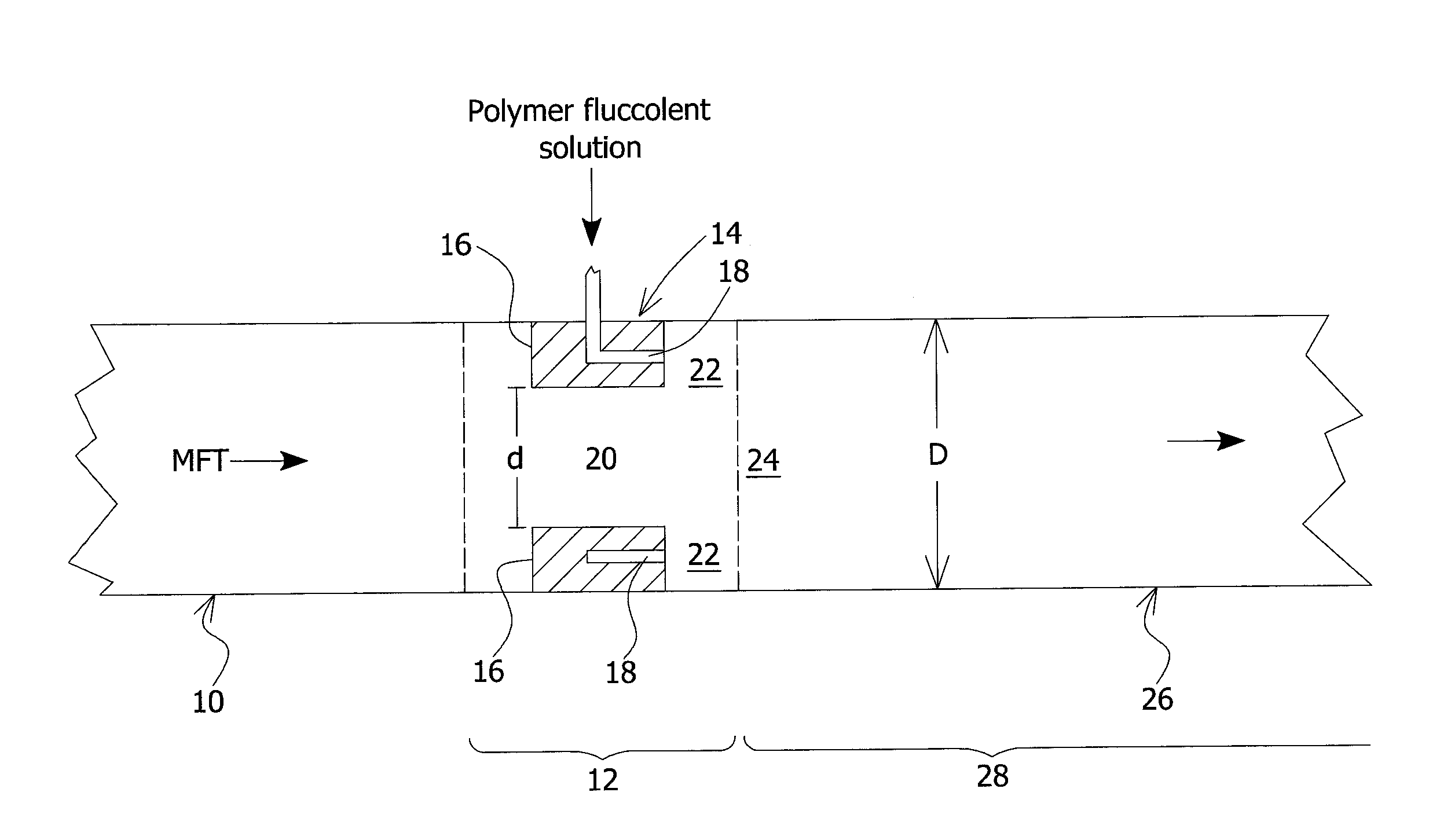
[0152]As mentioned in the above description, continuous flow pipeline reactor tests were conducted. Results are shown in FIG. 15 comparing high and low flow rates. A 34 wt % solids MFT was pumped through a 2 inch diameter pipe at a flow rate of 26 LPM for the low flow test and 100 LPM for the high flow test. A 0.45% organic polymer flocculent solution was injected at 2.6 LPM for the low flow test and at 10 LPM for the high flow test. The distance from injection to deposition was 753 inches or 376.5 pipe diameters. The 2 inch long orifice mixer had an orifice to downstream pipe diameter ratio d / D=0.32 with six 0.052 inch diameter injectors located on a 1.032 inch diameter pitch circle. For the high flow test the six injector diameters were increased to 0.100 inch.


PUM

PropertyMeasurementUnit
Fractionaaaaaaaaaa
Fractionaaaaaaaaaa
Temperatureaaaaaaaaaa

Abstract

A process for dewatering oil sand fine tailings is provided and comprises a dispersion and floc build-up stage comprising in-line addition of a flocculent solution comprising an effective amount of flocculation reagent into a flow of the oil sand fine tailings; a gel stage wherein flocculated oil sand fine tailings is transported in-line and subjected to shear conditioning; a floc breakdown and water release stage wherein the flocculated oil sand fine tailings releases water and decreases in yield shear stress, while avoiding an oversheared zone; depositing the flocculated oil sand fine tailings onto a deposition area to form a deposit and to enable the release water to flow away from the deposit, preferably done in a pipeline reactor and managing shear according to yield stress and CST information and achieves enhanced dewatering.

Description

FIELD OF THE INVENTION[0001]The present invention generally relates to the field of treating oil sand fine tailings.BACKGROUND[0002]Oil sand fine tailings have become a technical, operational, environmental, economic and public policy issue.[0003]Oil sand tailings are generated from hydrocarbon extraction process operations that separate the valuable hydrocarbons from oil sand ore. All commercial hydrocarbon extraction processes use variations of the Clark Hot Water Process in which water is added to the oil sands to enable the separation of the valuable hydrocarbon fraction from the oil sand minerals. The process water also acts as a carrier fluid for the mineral fraction. Once the hydrocarbon fraction is recovered, the residual water, unrecovered hydrocarbons and minerals are generally referred to as “tailings”.[0004]The oil sand industry has adopted a convention with respect to mineral particle sizing. Mineral fractions with a particle diameter greater than 44 microns are referre...

Claims


Application Information

Patent Timeline
IPC IPC(8): B01D21/01B01D21/24C02F1/52C02F11/147
CPCB01F5/0463B01F5/0466B01F2005/0034C02F2103/10C10G33/04C02F1/56C02F11/14C10G1/047C02F11/147B01F2025/918B01F25/31332B01F25/31331
Inventor REVINGTON, ADRIAN PETEROMOTOSO, OLADIPOWELLS, PATRICK SEANHANN, THOMAS CHARLESWEISS, MARVIN HARVEYBUGG, TREVOREASTWOOD, JAMIEYOUNG, STEPHEN JOSEPHO'NEILL, HUGUES ROBERTSANCHEZ, ANA CRISTINA
Owner SUNCOR ENERGY INC
Why Eureka
Try Eureka