Single structure cascode device

a single structure, transistor technology, applied in the direction of semiconductor devices, transistors, electrical devices, etc., can solve the problems of n-doping giving lower series resistance, affecting the performance of the device, and affecting the device's performance, so as to achieve the effect of reducing the loss of switching gates, reducing the cost, and reducing the cos

Inactive Publication Date: 2012-07-12
QUALCOMM INC
View PDF41 Cites 60 Cited by
  • Summary
  • Abstract
  • Description
  • Claims
  • Application Information

AI Technical Summary

Benefits of technology

[0027]The present invention describes a power transistor which has a MOS structure with drain extension, with an additional gate terminal that controls the carrier density in the drift region. This characteristic enables the use of short gate lengths while maintaining the electric field underneath the gate-drain edge within reasonable values in high voltage applications, without increasing the device on-resistance. Another inherent advantage is that the switching gate losses are smaller due to lower VGS voltages required to operate the device.

Problems solved by technology

The complementary CMOS components used in current integrated circuit process technologies have undergone a continuous shrinking of the silicon area needed for elementary components, however the need to further improve on its general performance while reducing its cost is still a necessity that poses a significant challenge.
This generally poses a penalty on the device performance such as lower transconductance and speed, which are strictly correlated to the Figure of Merit described above (RDSon*Q).
Yet at low drain bias its n-doping gives lower series resistance.
However, this advantage comes at the cost of the on-resistance which is higher than in standard MOSFETs due to the low doping concentration of the drift region.
Thus nowadays, no single device that offers combined benefits of a MOSFET (low forward voltage drop for high voltage applications) and a LDMOSFET (fast switching) exists.
Furthermore, the cascode configuration dramatically reduces the Miller feedback capacitance from the input FET gate to the output swing node.
This injection of charge carriers often results in a localized and non-uniform build-up of interface states and oxide charges near and underneath a gate and / or in the drift region of the device.
The control of the dummy gate on the carrier transport is therefore very limited.

Method used


Image

  • Single structure cascode device
  • Single structure cascode device
  • Single structure cascode device

Examples


second embodiment

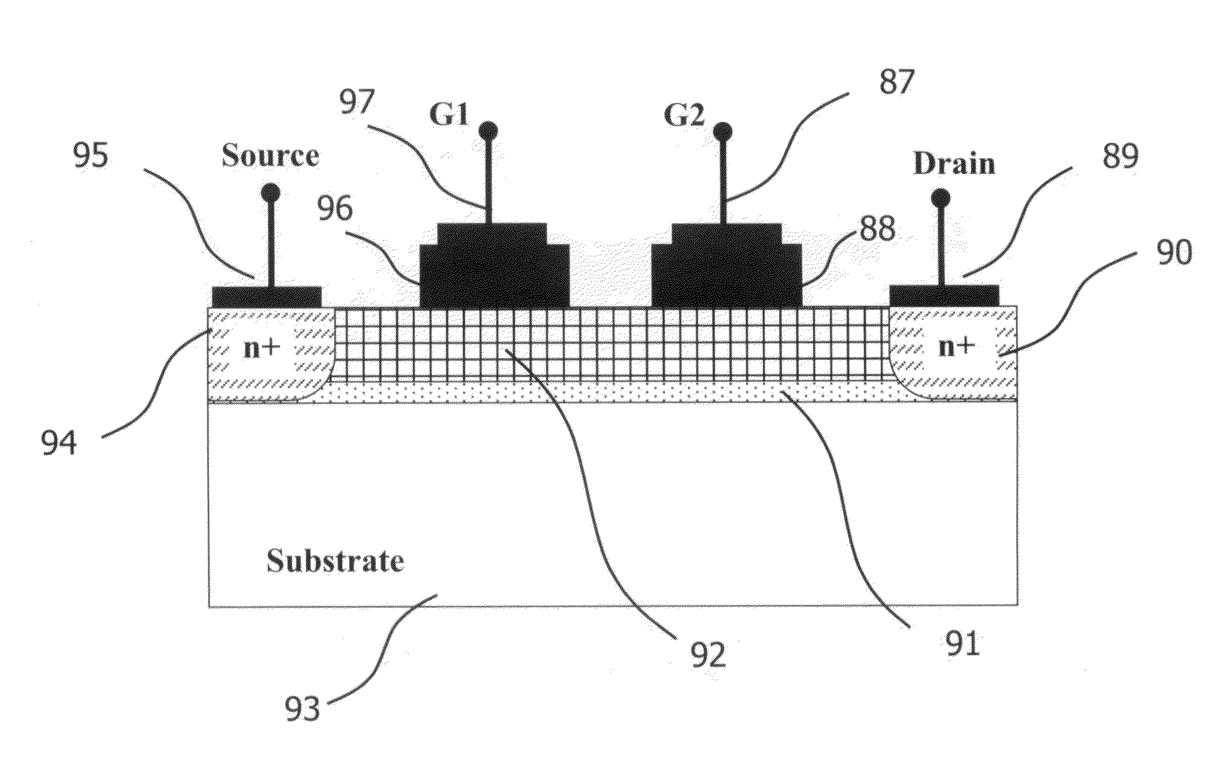
[0083]In FIG. 4 is shown the invention. This device structure has been obtained from an LDMOS by simply adding a second gate on the top of the drift region.

[0084]In this case, the channel length of the device is determined by the doping implants characteristics (e.g. impurity concentration, diffusivity and implants deepness) of the source and drain regions rather than the minimum feature size of the process technology used to realize the device. As mentioned above, this is a great advantage in power devices that usually are using process technologies that are not the most advanced, to reduce the fabrication cost.

C FIG. 5

third embodiment

[0085]FIG. 5 is depicting the cross-section view of a semiconductor device according to the invention. This structure is similar to the one shown in FIG. 3, with the exception that the channel region has been doped with n-type impurities and the gate layer 47 is p-doped. In this case, the impurity scattering and the surface roughness scattering rates are greatly reduced with respect to the structure of FIG. 3. This structure allows therefore the improvement of the carrier mobility in the device maintaining a positive threshold voltage and, therefore, an enhancement MOS behavior.

D FIG. 6

fourth embodiment

[0086]FIG. 6 illustrates a cross section of the invention. This structure is similar to the one of FIG. 3, with the exception that the extra gate is buried in the silicon substrate. This configuration allows the reduction of the capacitive coupling between the two gate terminals, which leads to an improvement of the dynamic performance of the device.

E FIG. 7

[0087]In FIG. 7 a metal (or heavily doped poly-silicon) layer connecting the source with the extra gate is present. In this case the second gate is biased at the source voltage and only the main gate region is connected to an external terminal during the device operation.


PUM


Abstract

A novel semiconductor power transistor is presented. The semiconductor structure is simple and is based on a MOS configuration with a drift region and an additional gate that modulates the carrier density in the drift region, so that the control on the carrier transport is enhanced and the specific on-resistance per area is reduced. This characteristic enables the use of short gate lengths while maintaining the electric field under the gate within reasonable values in high voltage applications, without increasing the device on-resistance. It offers the advantage of extremely lower on-resistance for the same silicon area while improving on its dynamic performances with respect to the standard CMOS technology. Another inherent advantage is that the switching gate losses are smaller due to lower VGS voltages required to operate the device.

Description

BACKGROUND OF THE INVENTION[0001]1. Field of the Invention[0002]The present invention is in the field of semiconductor structures. The present invention is further in the field of semiconductor structures of transistor devices. The present invention further relates to the field of integrated and non-integrated power devices and circuits. The implementation is not limited to a specific technology, and applies to either the invention as an individual component or to inclusion of the present invention within larger systems which may be combined into larger integrated circuits.[0003]2. Brief Description of Related Art[0004]The semiconductor transistor is the most important component for large integrated circuits. The complementary CMOS components used in current integrated circuit process technologies have undergone a continuous shrinking of the silicon area needed for elementary components, however the need to further improve on its general performance while reducing its cost is still ...

Claims


Application Information

Patent Timeline
Patent Type & Authority Applications(United States)
IPC IPC(8): H01L29/78H01L21/335H01L21/336H01L29/778H01L27/088
CPCH01L29/402H01L29/407H01L29/41775H01L29/7838H01L29/7787H01L29/7831H01L29/7835H01L29/42316
Inventor MARINO, FABIO ALESSIOMENEGOLI, PAOLO
Owner QUALCOMM INC
Why Eureka
Try Eureka