High Intensity Light Source

a high-efficiency, light source technology, applied in the field of lighting, can solve the problems of inability to immediately provide full brightness of fluorescent lights, many people are still reluctant to switch to these alternative light sources, and the lamps cannot be simply disposed of at the curbside, so as to increase the cost or size of the device, and achieve high-efficiency lighting sources. , the effect of increasing the cost of the devi

a high-efficiency, light source technology, applied in the field of lighting, can solve the problems of inability to immediately provide full brightness of fluorescent lights, many people are still reluctant to switch to these alternative light sources, and the lamps cannot be simply disposed of at the curbside, so as to increase the cost or size of the device, and achieve high-efficiency lighting sources. , the effect of increasing the cost of the devi

US20120187830A1Inactive Publication Date: 2012-07-26KORRUS INC

Image

  • High Intensity Light Source
  • High Intensity Light Source
  • High Intensity Light Source

Examples


Embodiment Construction

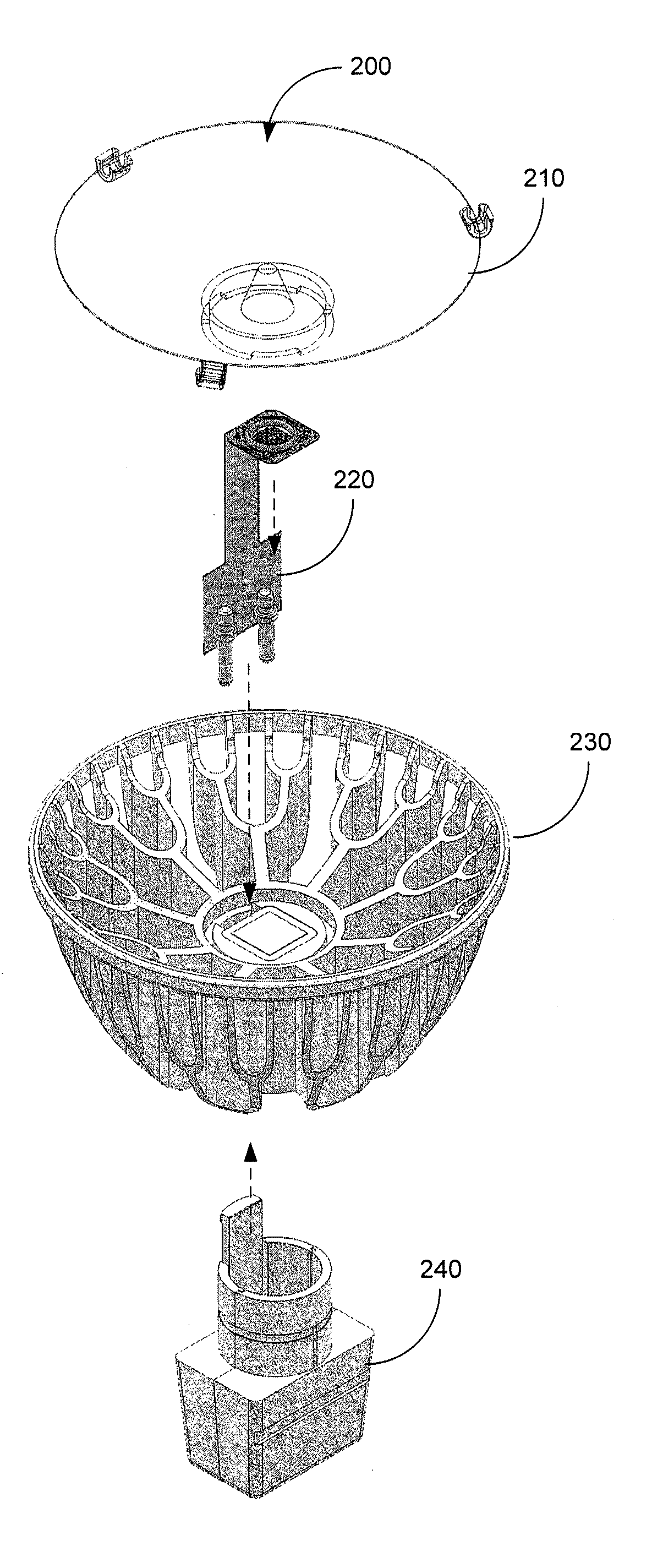
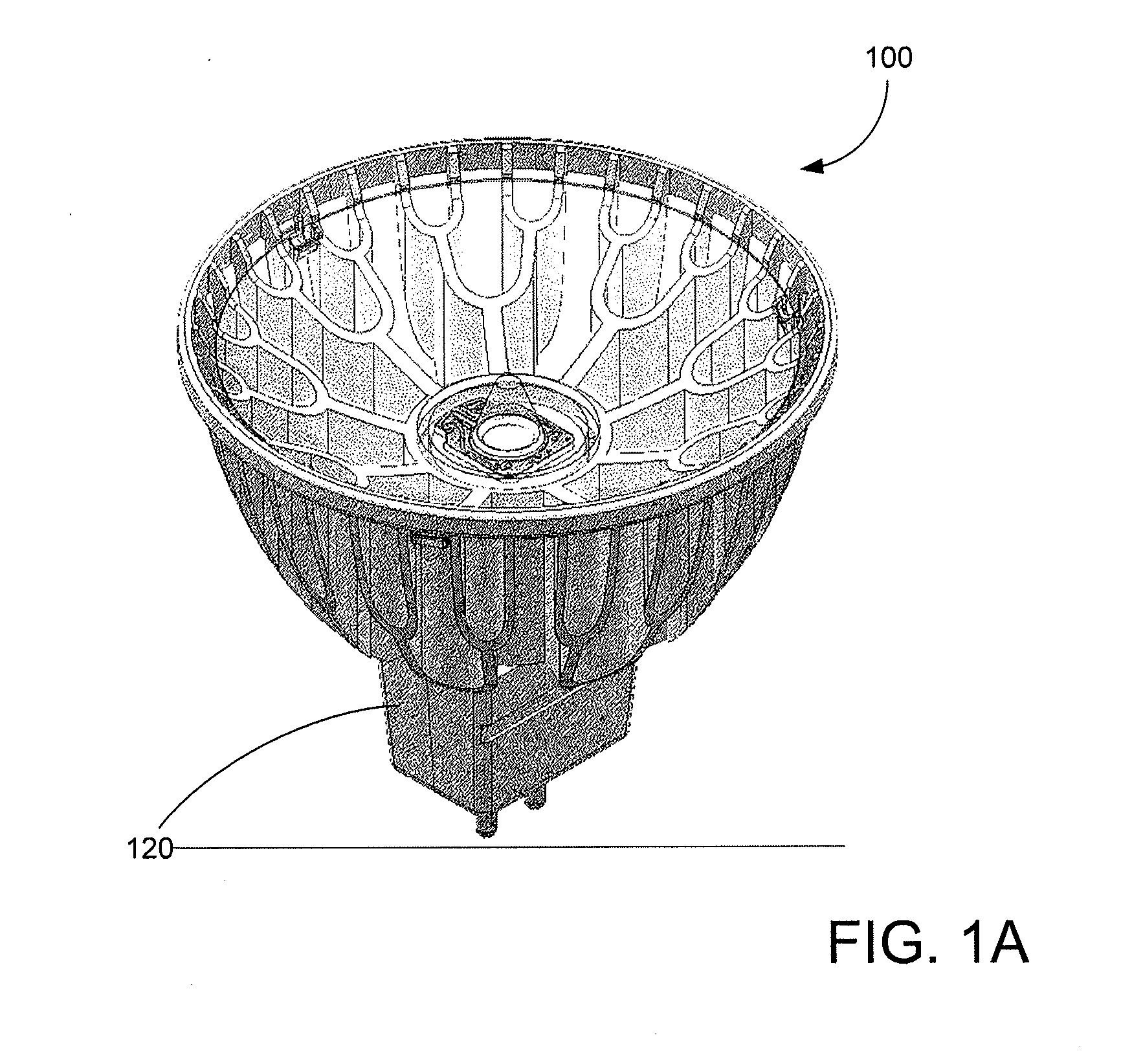
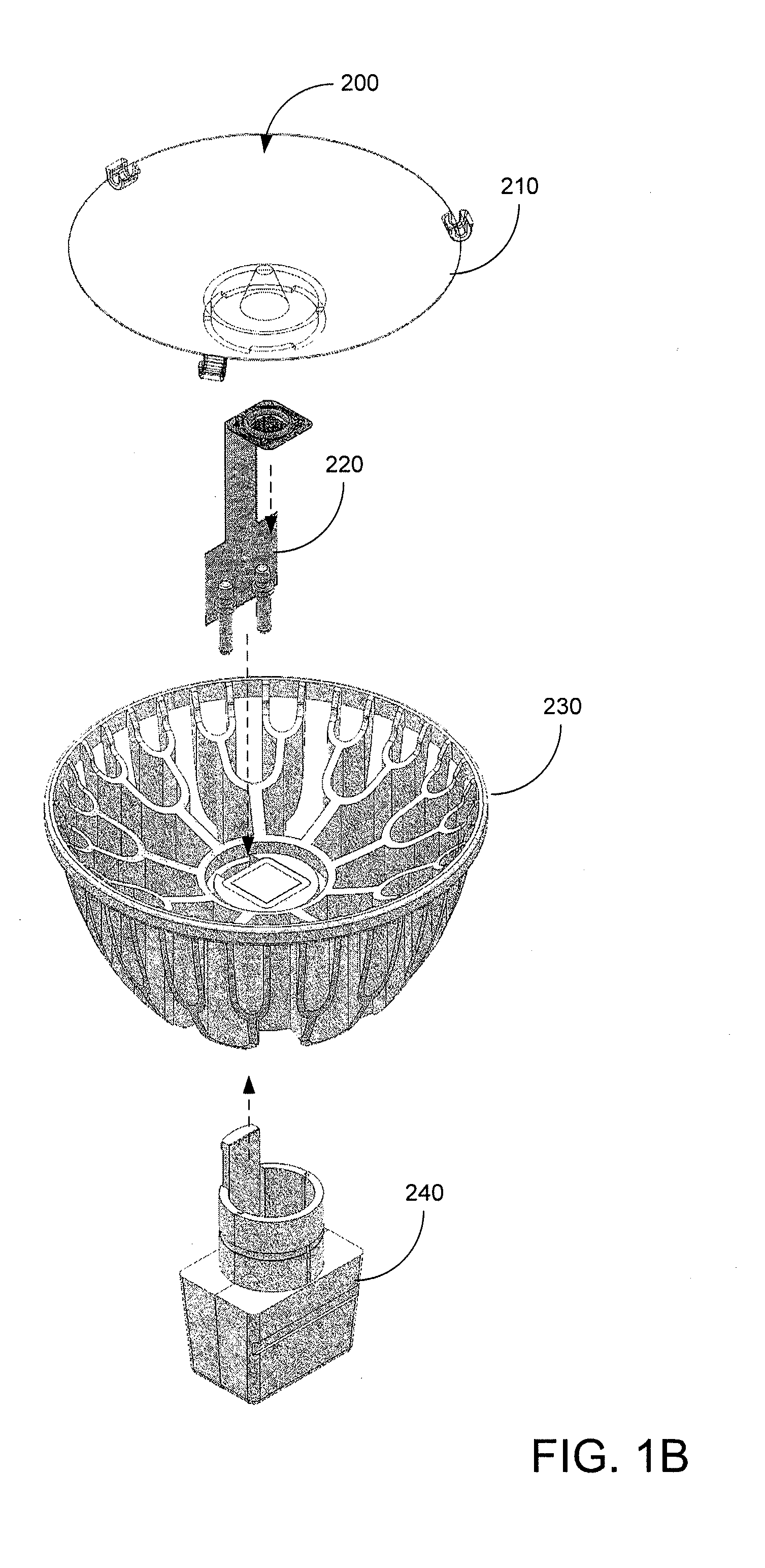
[0028]FIG. 1A illustrates an embodiment of the present invention. More specifically, FIG. 1A-B illustrate embodiments of MR-16 form factor compatible LED lighting source 100 having GU 5.3 form factor compatible base 120. MR-16 lighting sources typically operate upon 12 volts, alternating current (e.g. VAC). In the examples illustrated, LED lighting source 100 is configured to provide a spot light having a 10 degree beam size. In other embodiments LED lighting sources may be configured to provide a flood light having a 25 or 40 degree beam size, or any other lighting pattern.

[0029]In various embodiments, an LED assembly described in the pending patent applications described above, and variations thereof, may be used within LED lighting source 100. Theses LED assemblies are currently under development by the assignee of the present patent application. In various embodiments, LED lighting source 100 may provide a peak output brightness of approximately 7600 to 8600 candelas (with appro...


PUM

PropertyMeasurementUnit
angleaaaaaaaaaa
timeaaaaaaaaaa
poweraaaaaaaaaa

Abstract

A light source comprises a heat-sink having a mounting region, and heat-dissipating fins, a base housing having an inner cavity and coupled to the heat-sink, and an integrated lighting module including: a printed circuit board; an LED on a substrate coupled to the printed circuit board within a first lateral region of the printed circuit board, and an electronic driving circuit for providing power to the LED and coupled to the printed circuit board within a second lateral region of the printed circuit board, wherein a bottom surface of the substrate is thermally coupled to the mounting region of the heat-sink, and wherein the second lateral region of the integrated lighting module is located within the inner cavity of the base housing.

Description

CROSS-REFERENCE TO RELATED APPLICATIONS[0001]The present application relates to and claims priority to U.S. Provisional Patent Application No. 61 / 391,506, filed Oct. 8, 2010. This provisional patent application is incorporated herein by reference for all purposes.BACKGROUND[0002]The present invention relates to lighting. More specifically, the present invention relates to high efficiency lighting sources.[0003]The era of the Edison vacuum light bulb will be coming to an end soon. In many countries and in many states, common incandescent bulbs are becoming illegal, and more efficient lighting sources are being mandated. Some of the alternative light sources currently include fluorescent tubes, halogen, and light emitting diodes (LEDs). Despite the availability and improved efficiencies of these other options, many people have still been reluctant to switch to these alternative light sources.[0004]The inventors of the present believe that there are several key reasons why consumers ha...

Claims


Application Information

Patent Timeline
26 Jul 2012
Publication
US20120187830A1
IPC
F21V23/00; H05K3/30; B32B37/12; F21V17/00
CPC
H05K1/021; H05K1/189; H05K2201/10106; F21K9/137; F21V23/005; Y10T29/49826; F21V29/74; F21V29/77
Inventors
SHUM, FRANK TIN CHUNG; JUE, CLIFFORD