Energy storage system and method

a technology of energy storage and energy storage, applied in the direction of emergency power supply arrangement, hybrid vehicles, greenhouse gas reduction, etc., can solve the problems of generating environmental problems, battery replacement, and limited number of times a conventional battery may be charged again

Inactive Publication Date: 2012-07-26
UNIV LAVAL
View PDF6 Cites 31 Cited by
  • Summary
  • Abstract
  • Description
  • Claims
  • Application Information

AI Technical Summary

Benefits of technology

[0033]The energy storage system may provide high efficiency energy storage, particularly for medium and long term energy storage applications, which is of great advantage.
[0105]The energy storage system may also be useful to provide a reliable UPS (Uninterruptible Power Supply), which is of great advantage.

Problems solved by technology

However, as well known in the art, the number of times a conventional battery may be charged once again is limited.
The batteries must then be replaced very often, which is a great drawback, especially in applications where the batteries are frequently charged and discharged.
Moreover, conventional batteries, which typically use chemical acid and / or polluting elements such as lead, are also known to generate environmental issues.
Finally, aerodynamic losses are essentially the losses due to the friction of the rotating parts of the flywheel with the air, generally in a containment vessel surrounding the flywheel.
Minimizing those losses is not easy to achieve because they are all interrelated.
For instance, the reduction of friction losses can be achieved with magnetic bearings instead of mechanical bearings, but that particular embodiment will increase the magnetic and electric losses of the whole system.
They are however also known for their iron losses (magnetic losses) at no load and their short range of speed at a constant power, two major drawbacks for the flywheel storage systems of the art.
This method requires the over sizing of the supplying inverter and increases the losses of the inverter and of the motor-generator.
However, the disc of the flywheel has to be designed according to the peripheral speed limit of the material that composes the rotating disc.
Above that limit, the disc is subject to permanent deformation and breakages may occur, which is highly dangerous and thus undesirable.
Indeed, using a high rotational speed may be desirable to store more kinetic energy and to improve the storage duration but it will also increase the overall losses of the whole energy storage system.
Such electric power converters are however costly and they lack of reliability in certain circumstances.
The lack of reliability is caused principally by the junction temperature of the semiconductor (power transistor).
The trade-off, however, is the increase of the switching losses incurred and the increase of the power transistor temperature.
Thus, the use of an increased switching frequency generates an increase in power output losses of the inverter.

Method used


Image

  • Energy storage system and method
  • Energy storage system and method
  • Energy storage system and method

Examples


Embodiment Construction

[0139]In the following description of the embodiments, references to the accompanying drawings are by way of illustration of examples by which the invention may be practiced. It will be understood that other embodiments may be made without departing from the scope of the invention disclosed.

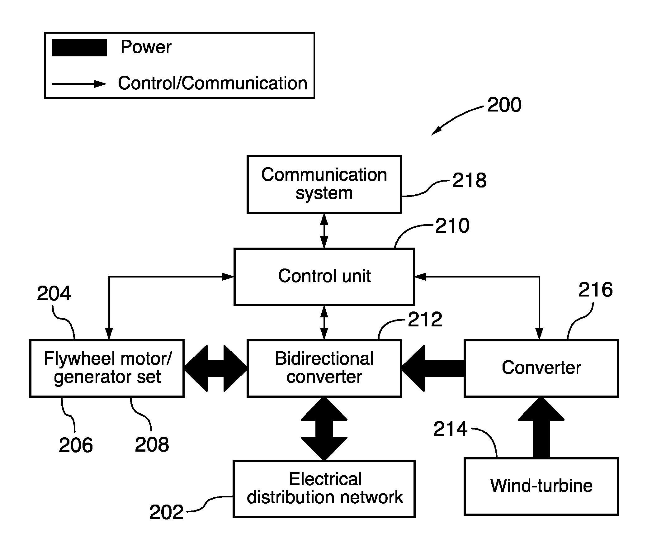
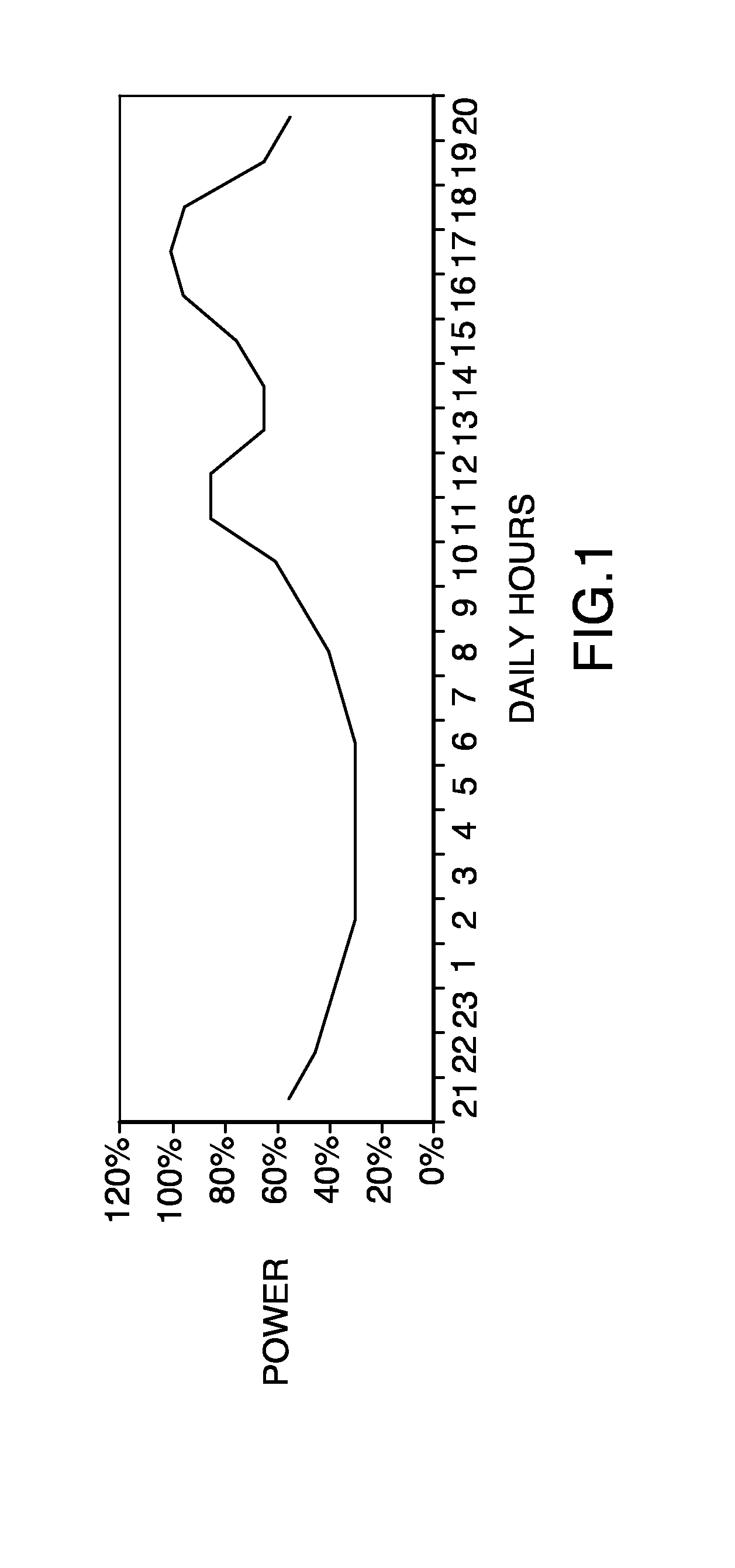
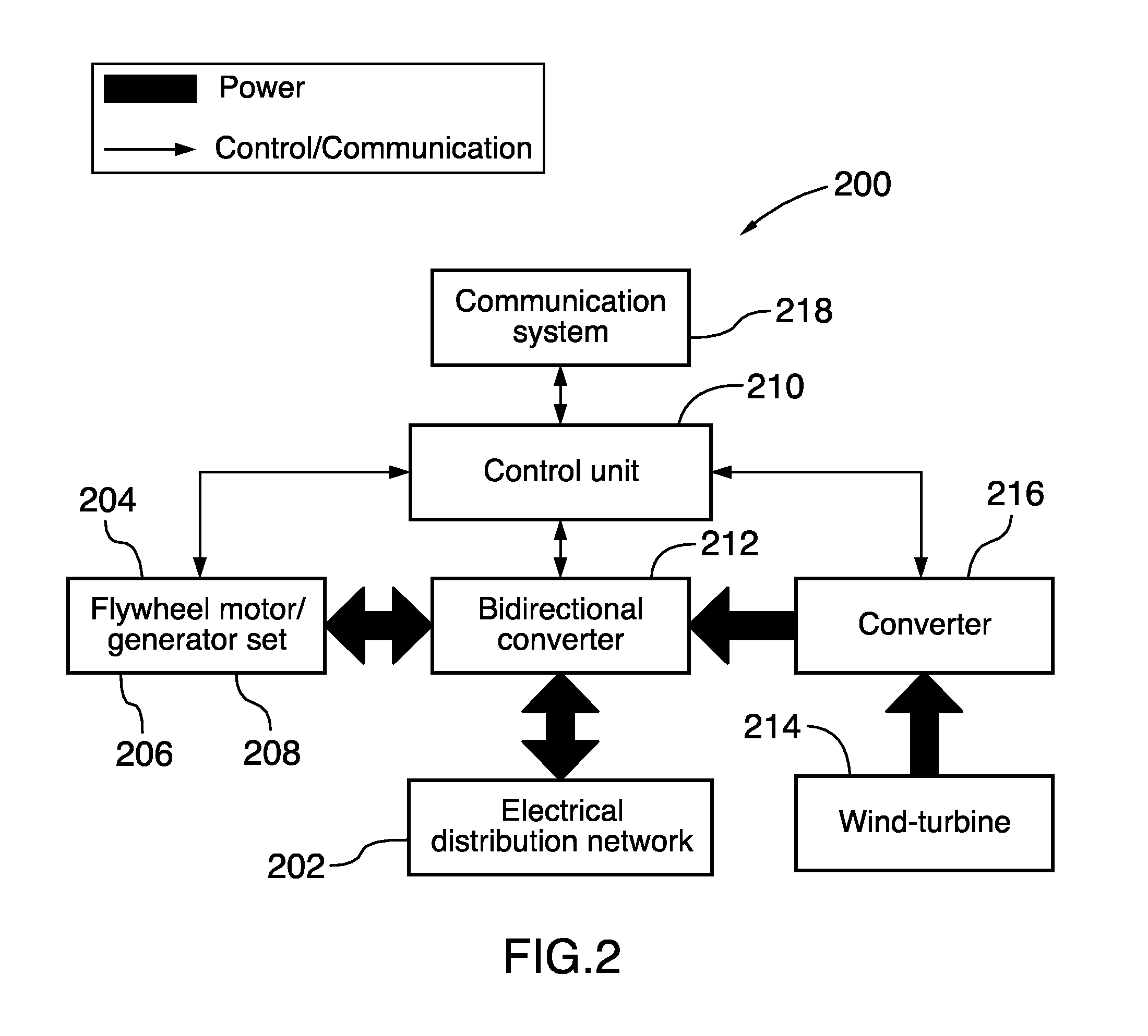
[0140]The invention relates to an energy storage system that may provide high efficiency energy storage, particularly for medium and long term energy storage applications. For example, the energy storage system may enable an energy conservation of 95% over a 24 hour period when no energy is extracted from the energy storage system. Moreover, the energy storage system may also enable a round trip efficiency, i.e. the transfer efficiency from the electrical grid to the storage system and from the storage system to the electrical grid again, of more than 85%.

[0141]As it will be more clearly understood upon reading of the present description, the energy storage system is reliable, may be maintained a...


PUM


Abstract

An system for storing electrical energy over at least a medium term duration. The energy storage system comprises a motor assembly operatively connectable to at least one of an electrical energy source and an electrical distribution network for providing kinetic energy, a flywheel device operatively connectable to the motor assembly for storing at least one part of the kinetic energy, a generator assembly operatively connectable to the flywheel device for receiving at least one portion of the part of the kinetic energy and generating regenerated electrical energy in response thereto, and a control unit for controlling operation of the energy storage system, which enables an energy storage operating mode for storing the part of the kinetic energy into the flywheel device, and an energy supply operating mode for providing at least one portion of the regenerated energy to at least one of the electrical distribution network and an electrical appliance.

Description

CROSS REFERENCE TO RELATED APPLICATIONS[0001]This application is a Continuation-in-Part Application of PCT International Application No. PCT / CA2010 / 000922, entitled “ENERGY STORAGE SYSTEM AND METHOD”, International Filing Date Jun. 15, 2010, published on Dec. 23, 2010 as International Publication No. WO 2010 / 145021, which in turn claims priority from U.S. Provisional Patent Application No. 61 / 187,170, filed Jun. 15, 2009, U.S. Provisional Patent Application No. 61 / 187,174, filed Jun. 15, 2009, U.S. Provisional Patent Application No. 61 / 187,176, filed Jun. 15, 2009 and U.S. Provisional Patent Application No. 61 / 233,664, filed Aug. 13, 2009, all of which are incorporated herein by reference in their entirety.[0002]This application is a Continuation-in-Part Application of PCT International Application No. PCT / CA2010 / 000919, entitled “DUAL SWITCHING FREQUENCY HYBRID POWER CONVERTER”, International Filing Date Jun. 15, 2010, published on Dec. 23, 2010 as International Publication No. WO ...

Claims


Application Information

Patent Timeline
Patent Type & Authority Applications(United States)
IPC IPC(8): H02K7/02
CPCB60K6/105Y10T74/2119H02J9/066H02J15/00H02K7/025Y02E10/725Y02E60/16Y02E70/30Y02T10/6204Y02T10/6269Y02T10/90H02J3/381H02J3/383H02J3/386Y02E10/563Y02E10/763H02J3/382H02M7/5388Y04S10/126Y02E60/721Y02T10/6282Y10T74/212F16F15/305H02J2300/40H02J2310/48H02J2300/28H02J2300/20H02J2300/24Y02B10/70Y02E10/56Y02E10/76Y02E10/72Y02T10/62H02J15/007Y02E60/00
Inventor DUBOIS, MAXIME R.DESJARDINS, MICHAELTREMBLAY, LOUIS
Owner UNIV LAVAL
Why Eureka
Try Eureka