Antenna duplexer

a duplexer and antenna technology, applied in the field of antenna duplexers, can solve the problems of low insertion loss and high attenuation, and the spurious emission of the resonator, etc., and achieve low insertion loss, high isolation characteristic, and high attenuation.

Active Publication Date: 2012-07-26
SKYWORKS PANASONIC FILTER SOLUTIONS JAPAN
View PDF3 Cites 39 Cited by
  • Summary
  • Abstract
  • Description
  • Claims
  • Application Information

AI Technical Summary

Benefits of technology

[0012]This antenna duplexer has a high attenuation characteristic and

Problems solved by technology

This configuration hardly provides an antenna duplexer with both of a low insertion loss and a high attenuation.
However, the one-port resonator producing the spurious emission has high impedance between a spurious resonance frequency and a main resonance frequency.
This provides the filter with a poor attenuation characteristic at a frequency causing the high impedance, thus failing to provide a high attenuation characteristic.
However, this configuration causes insufficient spurious resonance freque

Method used


Image

  • Antenna duplexer
  • Antenna duplexer
  • Antenna duplexer

Examples


Embodiment Construction

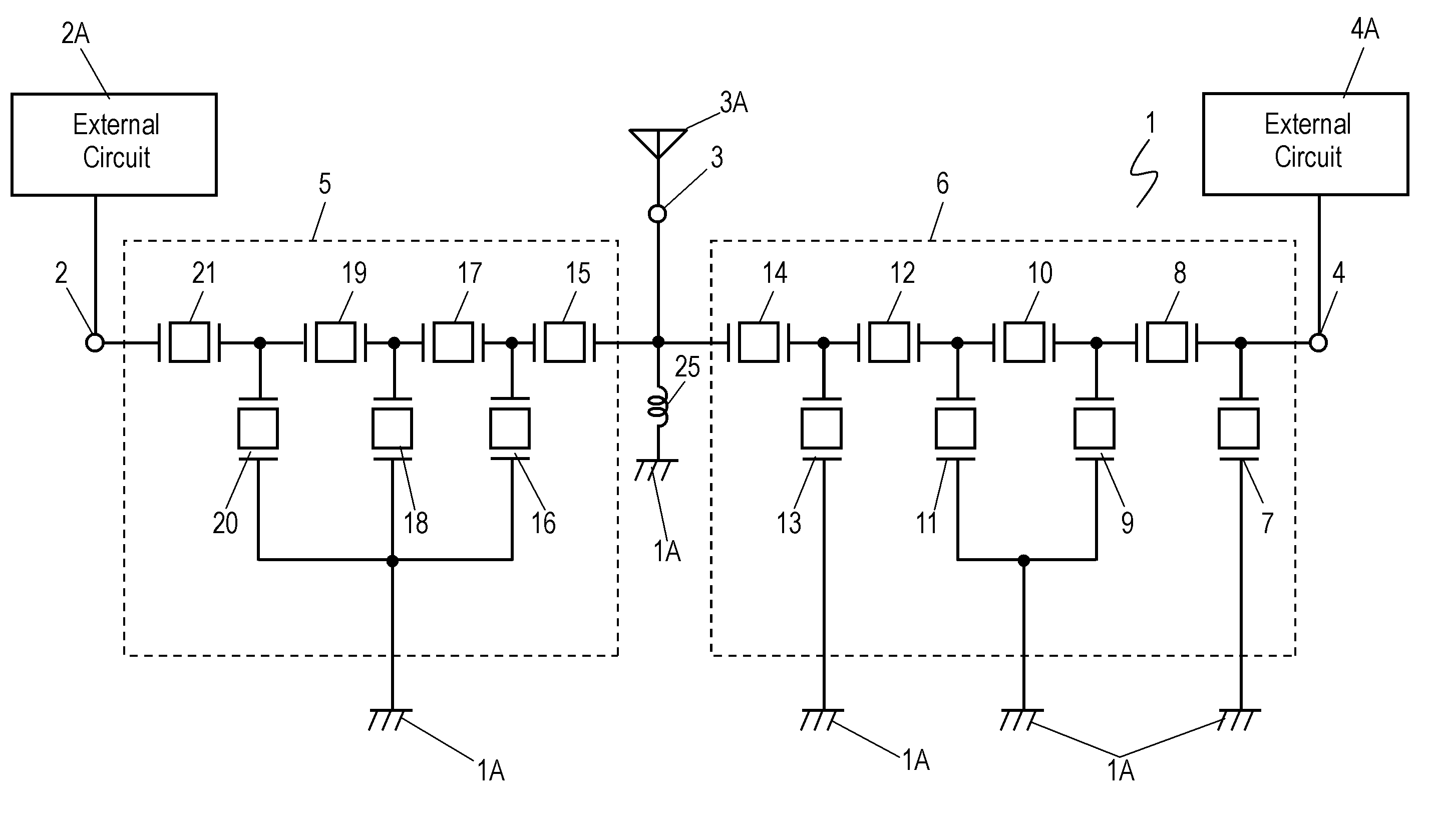
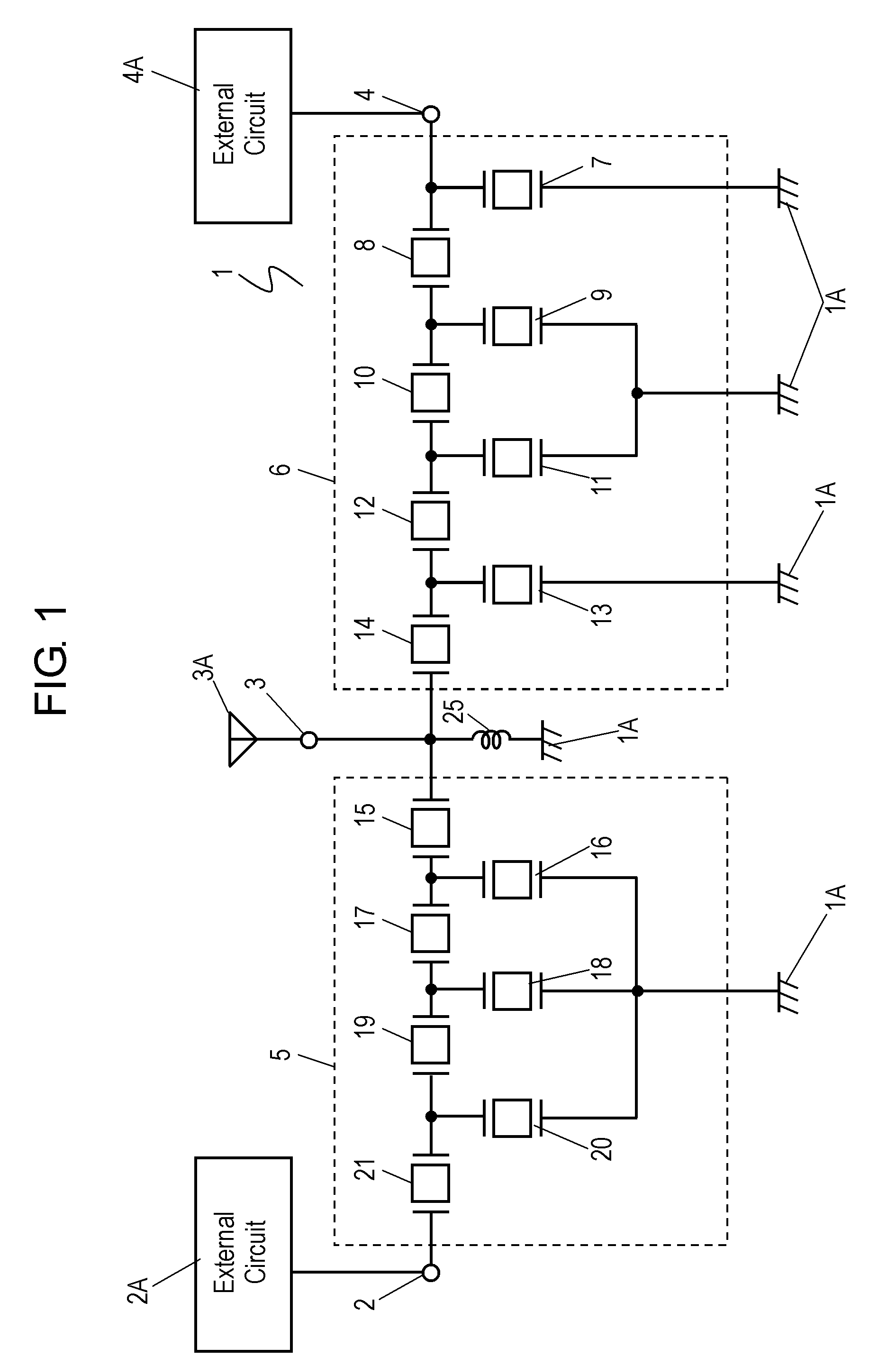
[0026]FIG. 1 is a circuit diagram of antenna duplexer 1 according to an exemplary embodiment of the present invention. Antenna duplexer 1 includes input terminal 2 for receiving a transmission signal, antenna terminal 3 configured to be connected to antenna 3A, output terminal 4 for outputting a reception signal, filter 5 connected between input terminal 2 and antenna terminal 3 in series, and filter 6 connected between output terminal 4 and antenna terminal 3 in series. Filter 5 has a passband of a low frequency band. Filter 6 has a passband of a high frequency band higher than the low frequency band. The high frequency band has the lowest frequency higher than the highest frequency of the low frequency band. Antenna duplexer 1 further includes inductor 25 connected between antenna terminal 3 and ground 1A. Inductor 25 functions as a phase shifter to provide the impedance matching between filters 5 and 6 at antenna terminal 3. Input terminal 2 is configured to be connected to exter...


PUM


Abstract

An antenna duplexer includes first and second filters connected to an antenna terminal. The first filter has a passband of a low frequency band. The second filter has a passband of a high frequency band. The second filter is a ladder-type filter including series-arm resonators and parallel-arm resonators. At least one parallel-arm resonator out of the parallel-arm resonators has a main resonance and an auxiliary resonance. Attenuation poles caused by the main resonance and the auxiliary resonance are within the low frequency band. This antenna duplexer has a high attenuation characteristic and a high isolation characteristic while maintaining a low insertion loss.

Description

FIELD OF THE INVENTION[0001]The present invention relates to an antenna duplexer that is mainly used in an electronic device, such as a mobile phone, and that branches a transmission wave and a reception wave.BACKGROUND OF THE INVENTION[0002]In recent years, a demand for antenna duplexers has been increasing due to a rapid spread of mobile phones using a communication system, such as Wideband Code Division Multiple Access (W-CDMA), performing simultaneous transmission and reception. Antenna duplexers are implemented by small, low profile, and mass-productive acoustic wave elements, such as a surface acoustic wave (SAW) element, a boundary elastic wave element, or a bulk acoustic wave element.[0003]An antenna duplexer generally includes a transmission filter and a reception filter in order to branch a transmission band signal and a reception band signal higher than the reception band signal. These filters may often employ ladder-type filters including series-arm resonators and parall...

Claims


Application Information

Patent Timeline
IPC IPC(8): H03H9/72
CPCH03H9/14535H03H9/725H03H9/6483H01P1/205H03H9/205H03H9/25H04B1/0057
Inventor YAMAJI, TORUNISHIMURA, KAZUNORIFUJIWARA, JOJINAKAMURA, HIROYUKI
Owner SKYWORKS PANASONIC FILTER SOLUTIONS JAPAN
Why Eureka
Try Eureka