Ionic impurities rejection and chromatographic purification using ion exchange

Inactive Publication Date: 2012-07-26
ROSSITER GORDON
View PDF7 Cites 1 Cited by
  • Summary
  • Abstract
  • Description
  • Claims
  • Application Information

AI Technical Summary

Benefits of technology

[0007]The invention uses a continuous ion exchange (CIX) system to first remove a species of interest (species A for example), using a suitable resin that exhibits selectivity for this species of interest while simultaneously adsorbing other non-desired species, (B, C, etc, for example); and then which further enhances the resin selectivity to continuously produce a pure product solution of species A by utilizing the product species, A, as a displacing ion in the same CIX system.
[0010]The adsorbent after ELUTION is typically rinsed in a RINSE step and may require conditioning with either dilute acid or dilute base. Acid conditioning prevents possible metal hydroxide precipitates from forming in the next ADSORPTION step. Conditioning with base may be required to enhance adsorption of the target species in the next ADSORPTION.
[0011]The above technique produces a stream of pure salt product at a strength which depends on the molarity of ELUENT utilized. Further, the co-loaded “impurities” having any significant value can be subsequently purified using a different resin / absorbent in a manner as set forth for the main processing stream. Further, a system may be set up for continuous process flow which will result in a continuous supply of pure product and which can run continuously neglecting any structural breakdown of the resin / absorbent.
[0017]2) An resin of weaker ionic strength, whether weaker acid or weaker base) than the strength of the eluent. It is precisely the ability of the strong eluent to effectively & efficiently return the resin to its “free form” that makes the process work.
[0024]In the case of elution, the incoming strong ionic eluent species which is used to completely return an absorptive resin to its “free form”, produces a zone of un-bound free form resin and a zone of not yet eluted pure target ion on the resin, with a zone boundary between them. At the beginning of the pre-elution step, this zone boundary is close to the inlet or front end of the resin and flow can be high as there are many sites available downstream to perform complete displacement to the “free form” state. However, as this zone boundary drifts forward, the eluent flow can be reduced to give more residence time of eluent and over a shorter length of resin in the zone of yet to be completely displaced target ion to ensure that waste eluent in the leaving target ion stream is reduced, and so that the strong ionic eluent has an opportunity to completely displace target ions with as little eluent as possible to avoid diluting the target ion stream with excess eluent. Such reduction in flow can be obtained automatically and in response to a variety of monitoring techniques including conductivity and / or pH measurements commonly indicate the position or direction of “drift” of these zone boundaries, or fronts.
[0029]4) the above three operations can then be coordinated and controlled using a controller or CIX system such as the IXSEP-RDA which facilitates & automates the operations shown in FIGS. 1 & 2;

Problems solved by technology

The ability of these to produce a high quality concentrated product is limited.

Method used


Image

  • Ionic impurities rejection and chromatographic purification using ion exchange
  • Ionic impurities rejection and chromatographic purification using ion exchange
  • Ionic impurities rejection and chromatographic purification using ion exchange

Examples


Embodiment Construction

[0038]The present apparatus and method can be applied to a variety of extractive industries and focuses upon the main idea of using a displacing pre-elution enrichment in an ion exchange system to produce a product stream of higher concentration, and more particularly of higher purity (such as a pure uranyl salt solution, for example). The preferably continuous ion exchange (CIX) implementation of this invention gives all the further advantages of continuous operation.

[0039]The apparatus utilized may have volumes and net material balances in each segment of the operation which may or may not balance and which may involve some net excess output or input and further treatment especially as to the eluent. Further, additional treatment of secondarily valuable species can occur, but will not be shown in the diagrams for purposes of simplicity of the diagram.

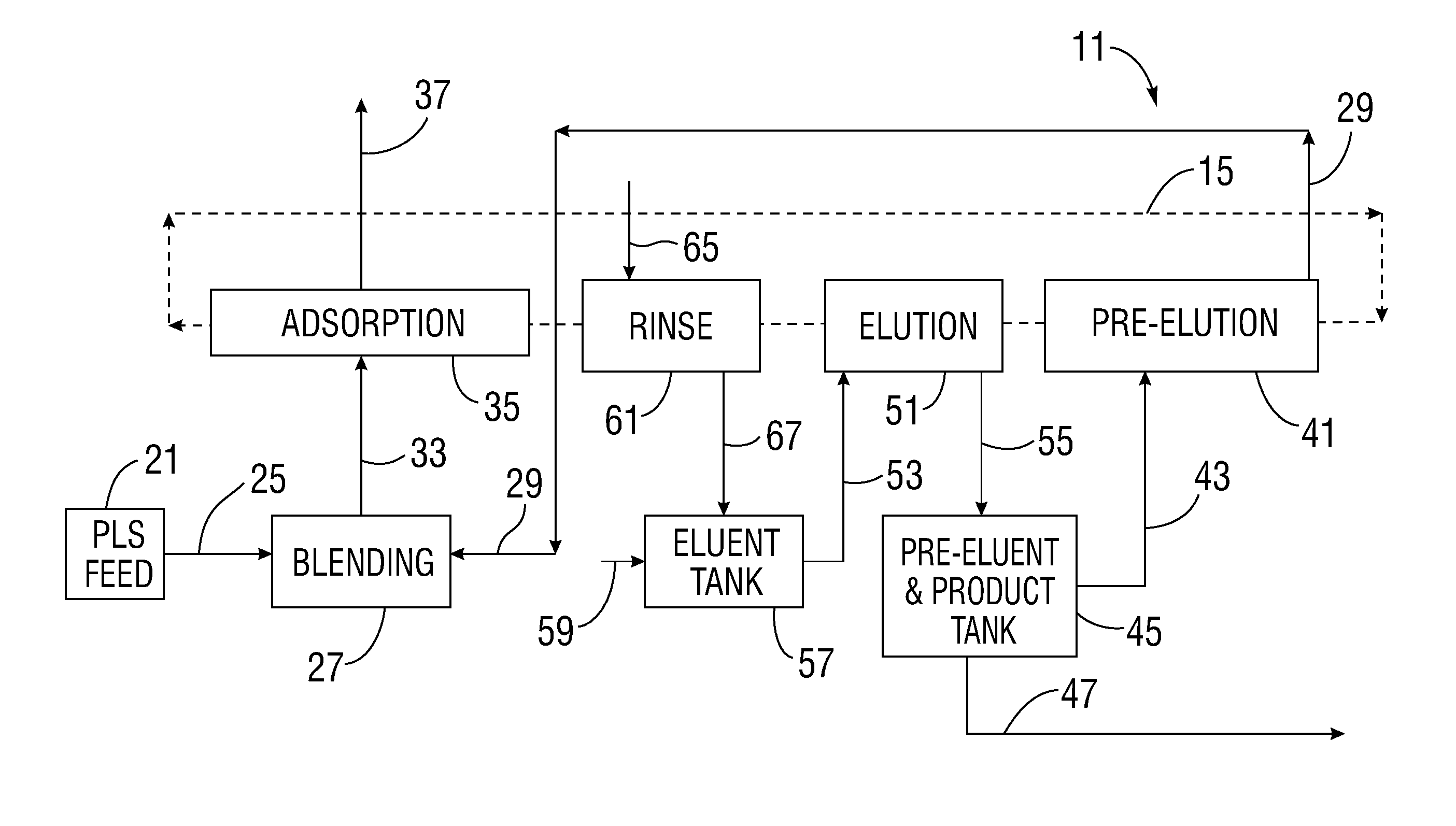
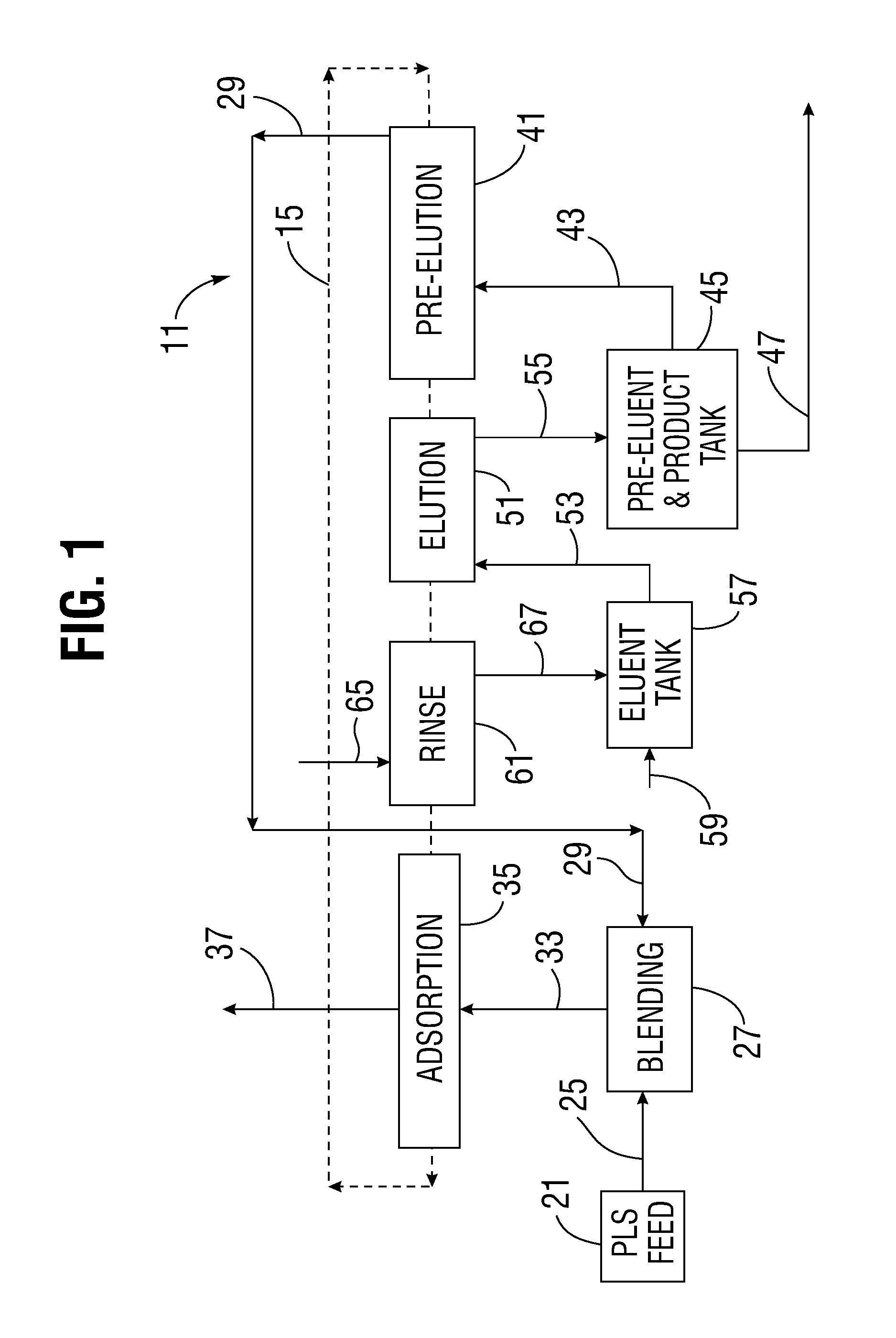
[0040]Referring to FIG. 1, an overall schematic diagram of an ion exchange purification system 11 is shown. The schematic diagram is...


PUM

PropertyMeasurementUnit
Selectivityaaaaaaaaaa

Abstract

The invention covers the combination of utilizing the selectivity of an adsorbent to remove species from a liquid containing mixtures of ions and then subjecting the loaded resin to a chromatographic displacement utilizing the most selectively adsorbed species to displace the undesired co-adsorbing impurities. The technique can be used even when the most selectively adsorbed species is present as a minor constituent in the feed solution.

Description

[0001]This application is a continuation-in-part application of co-pending U.S. patent application Ser. No. 13 / 010,753 filed Jan. 20, 2011.BACKGROUND OF THE INVENTION[0002]The present invention relates a combination of techniques to produce a high purity metal salt product utilizing the selectivity of an adsorbent to remove species from a liquid containing mixtures of ions and then subjecting the loaded resin to a chromatographic displacement utilizing the most selectively adsorbed species to displace undesired co-adsorbing impurities, and regardless of whether or not the most selectively adsorbed species is present as a minor constituent in the feed solution.[0003]Chromatographic purifications have been used on an analytical scale for many decades. Continuous chromatography has been able to be practiced on a production scale only in several selected industries (e.g., corn syrup industry sugar separations) as well in applications for rare earth separations & purifications.[0004]Tech...

Claims


Application Information

Patent Timeline
IPC IPC(8): C01G56/00C01D3/04C25C1/00C01G47/00C22B9/02C25B1/00
CPCC01G43/00C01G47/00C01D3/04C22B60/0265C22B61/00C22B3/24Y02P10/20C22B3/42
Inventor ROSSITER, GORDON
Owner ROSSITER GORDON
Why Eureka
Try Eureka