

Detection apparatus
a detection apparatus and reagent technology, applied in the field of detection apparatuses, can solve problems such as difficulty in portability and/or construction of specialized equipment, inability to meet the conditions experienced in the field, and difficulty in developing point-of-care tests for low abundance target molecules, so as to achieve low cost of expensive reagents and low fabrication costs
- Summary
- Abstract
- Description
- Claims
- Application Information
AI Technical Summary
Benefits of technology
Problems solved by technology
Method used
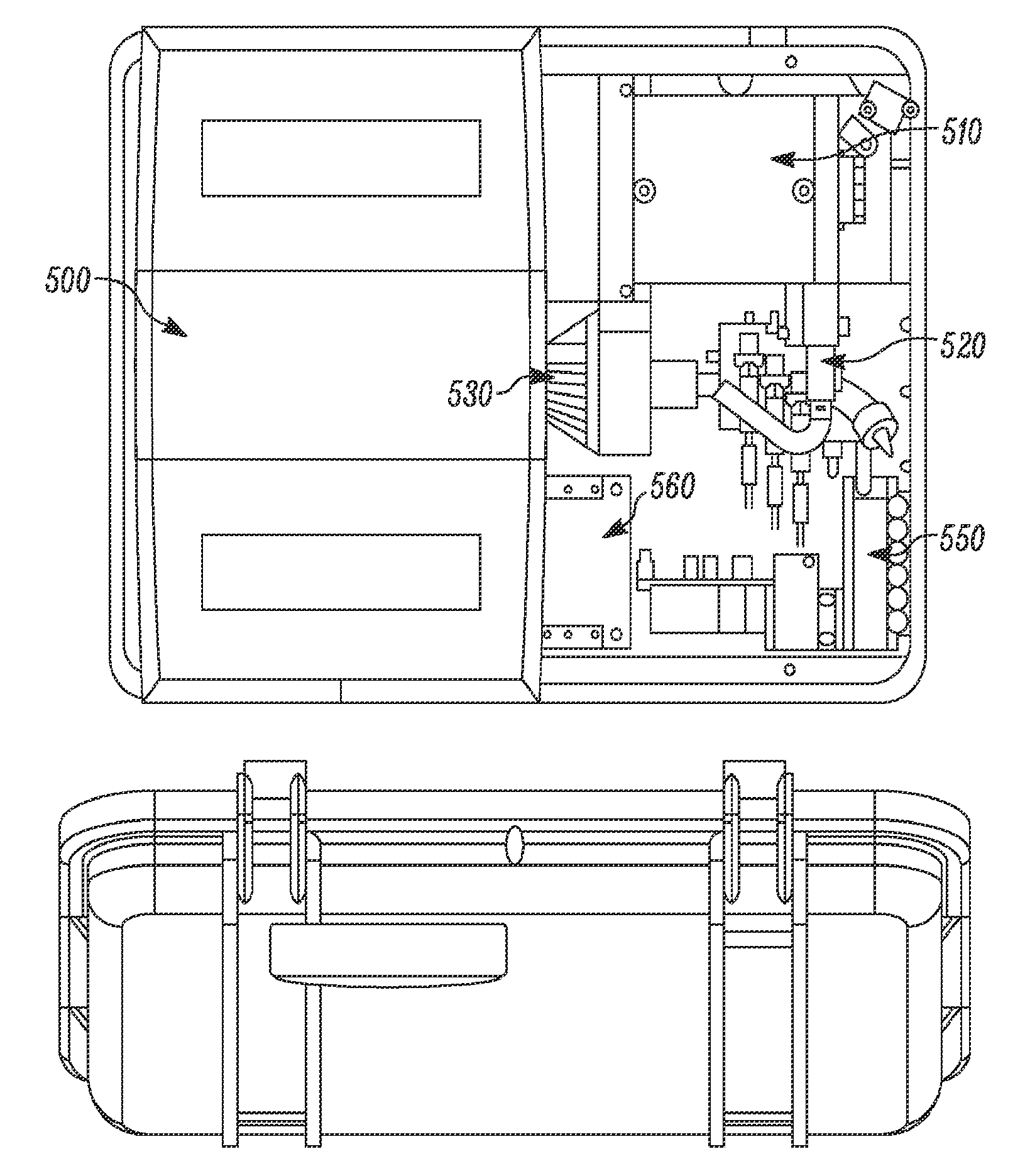
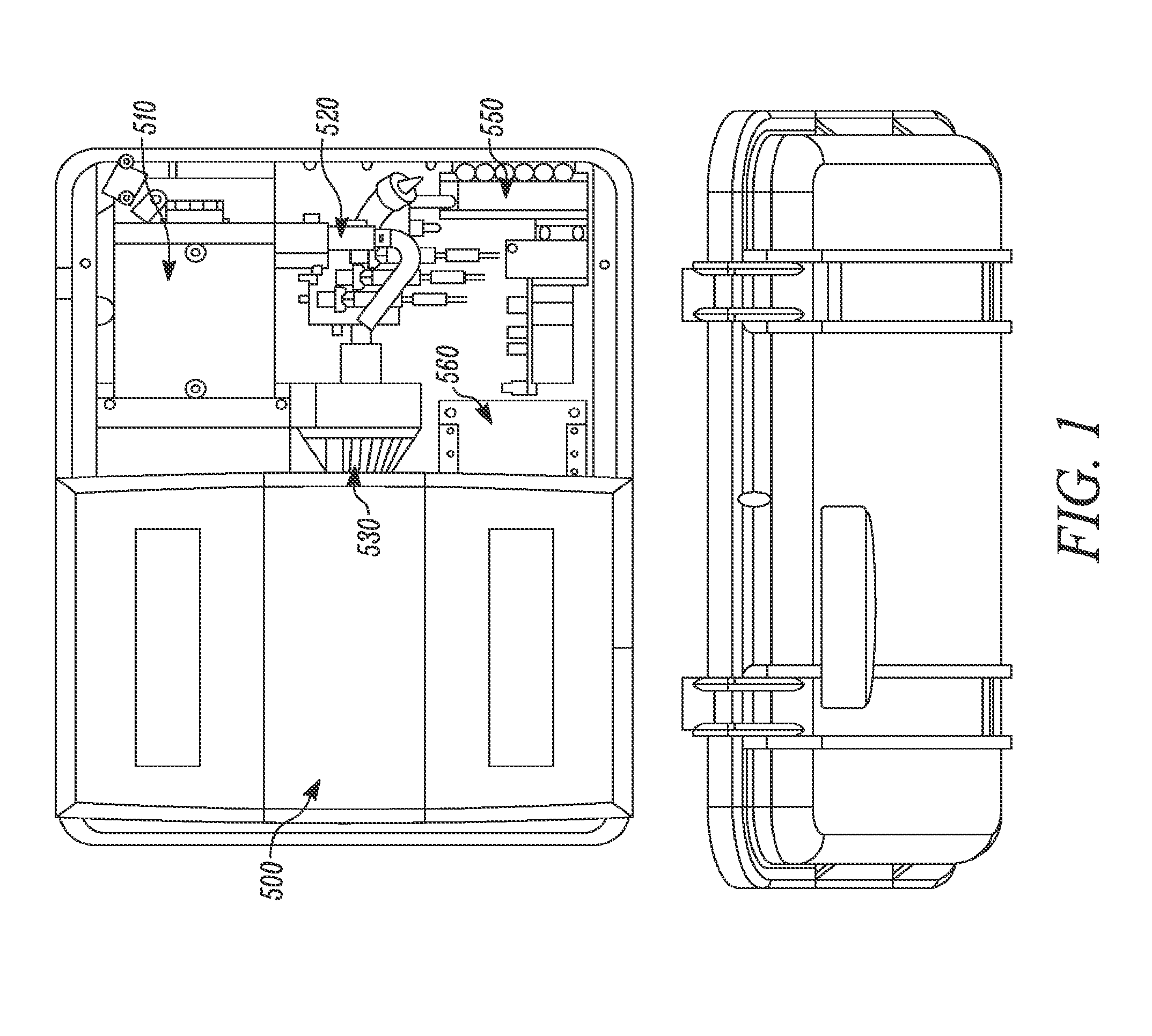
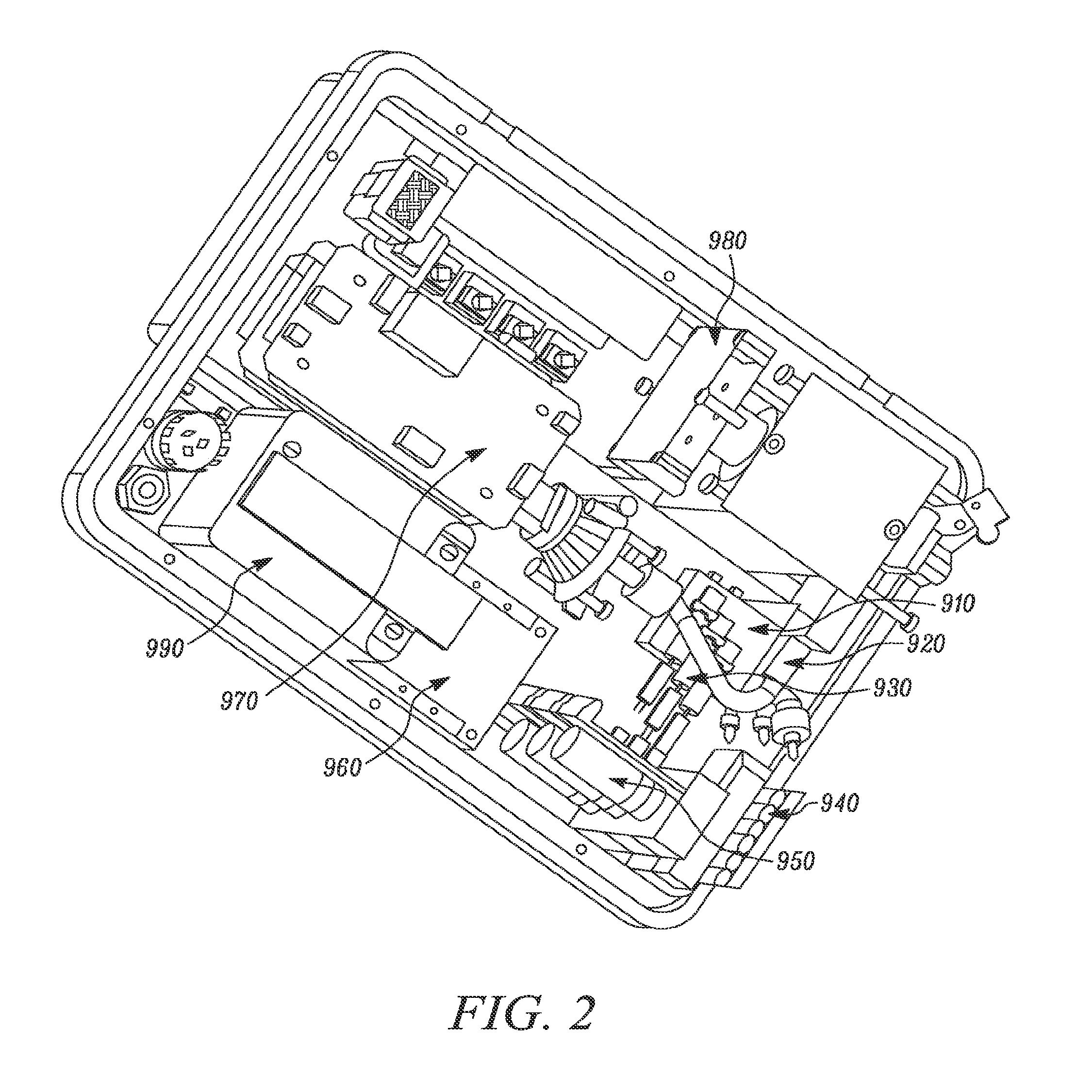
Image

Examples
example 1
Exemplary Antigens and Antibodies
[0404]Some agents utilized in related experiments included: B. anthracis Protective Antigen (PA); B. globigii, a simulant for gram-positive bacteria; Staphylococcal enterotoxin B; C. botulinum toxoid A; Y. pestis; and Ricin A chain. Most agents and antibodies used were kindly supplied by the Critical Reagents Program (CRP) of the Department of Defense (DOD). For results from some field assays, agents were supplied by the DOD and in some cases were not inactivated.
[0405]The antibodies above can be utilized as capture and / or detector binding molecules for the above agents. These include the following antibodies from the CRP: anti-anthrax E-062303, anti-B. globigii J-290501-03, anti-SEB 060299-01, anti-Botulinum toxin J-280800-01, anti-Y. pestis N-190803-01, and anti-ricin R-1054. In some cases, the same antibody is used as the detector and capture antibody, except that the detector antibody may comprise a label or tag.
example 2
An Example of Threat Detection Sensitivity and Specificity Data Using an RLS Assay
[0406]The following results were obtained using a prototype assay and assay chamber. Testing was performed on government furnished samples without knowledge of their content. All samples represented live organisms and active toxins. Testing was performed under ‘field conditions’ in a trailer at the U.S. Government's Dugway Proving Ground in Utah.
[0407]1,074 data points were collected from 358 samples over 12 days of testing resulting in one false positive (0.09%). Results are shown in Table 2
TABLE 2Anthrax (CFU / ml)BoToxA ng / mlYersinia CFU / mlBlank10626 / 26100%10224 / 24100%10524 / 24100%—29 / 29100%10535 / 35100%10129 / 3291%10429 / 29100%10426 / 3379%10023 / 2688%10324 / 3080%103 0 / 230%10−1 5 / 2124%102 0 / 210%
example 3
Examples of Readouts from Different Array Configurations
[0408]An array of spots / sites of capture antibody (anti B. anthracis) is placed on a substrate / reactive surface using a Biodot spotter (BioDot, Inc, Irvine, Calif.). Spotting is typically performed in volumes between about 10 nanoliters (nl) to 20 nl) Typically, the capture antibodies are spotted in a carbonate buffer such as sodium bicarbonate or calcium bicarbonate. In some cases, a spotting solution comprises dimethyl sulfoxide (DMSO), e.g., at 1%. Usually the carbonate buffer is of an acidic pH, e.g., about 8 to about 9, about 9 to about 10, about 10 to about 11, about 11 to about 12, about 12 to about 13, about 13 to about 14, or about 9.6. Spotting solutions typically contain antibodies at a concentration of between from about 1 to about 10 mg / ml.
[0409]Agent (inactivated, so as not pathogenic) is added to the spotted capture binding molecule, followed by biotinylated detector antibody and RLS gold-anti-biotin particles.
[0...
PUM
| Property | Measurement | Unit |
|---|---|---|
| volume | aaaaa | aaaaa |
| volume | aaaaa | aaaaa |
| volume | aaaaa | aaaaa |
Abstract
Description
Claims
Application Information