Optical recording and reading method, optical recording and reading apparatus, optical recording medium, and method for producing an optical recording medium

a recording medium and optical recording technology, applied in the direction of manufacturing tools, instruments, disposition/mounting of heads, etc., can solve the problems of increasing production costs, complicated medium configuration, and difficult eccentricity adjustment work, so as to improve the signal quality of recording and reading, always stably performing tracking control, and improving the transfer rate

Inactive Publication Date: 2012-08-09
TDK CORPARATION
View PDF10 Cites 7 Cited by
  • Summary
  • Abstract
  • Description
  • Claims
  • Application Information

AI Technical Summary

Benefits of technology

[0042]According to the present invention, for the optical recording medium including the servo layers and the recording and reading layers, it is possible to record information on the recording and reading layers while always stably performing the tracking control for the optical recording medium.
[0043]According to the present invention, in the optical recording medium including the servo layers and the recording and reading layers, it is possible to improve the signal quality in recording and reading.
[0044]Moreover, it is possible to improve the transfer rate even if the multiple recording and reading layers are provided in the optical recording medium.
[0045]Furthermore, for the optical recording medium including the servo layers and the recording and reading layers, it is possible to efficiently perform recording and reading, while suppressing the warpage or the deformation.
[0046]It is possible to suppress the complication of the optical pickup in the optical recording and reading apparatus, while increasing the number of the recording and reading layers, and to efficiently perform recording and reading.

Problems solved by technology

On the contrary, if the multiple recording and reading layers are provided in the optical recording medium, formation of concavo-convex patterns such as grooves / lands for tracking control on each recording and reading layer leads to a complicated medium configuration, causing concern about difficult eccentricity adjustment work and the like.
Thus, a larger number of layers increases the number of times of use of this stamper, and accordingly increases production costs.
WO2008 / 099708, an increase in the number of the recording and reading layers causes the number of the recording layers having the concavo-convex patterns and the grooves to increase, which, after all, leads to the complicated medium configuration, the difficult eccentricity adjustment work and the like.
As a result, when the thickness tolerance becomes large, a focus position of the tracking beam varies to destabilize the tracking signal, which causes a problem that sufficient tracking control cannot be performed.
Correction of the thickness tolerance is, however, limited, and the introduction of the focus servo mechanism also causes a problem of a large optical pickup.
For example, there has been a problem that a tracking position is greatly shifted from a recording position on a warped optical recording medium or the like.
As a result, there has been a disadvantageous problem with comatic aberration caused by a tilt or the like in recording and reading.
WO2008 / 099708, for example, there has been a problem that, when the beam dedicated to recording and reading passes through a desired recording and reading layer, this leakage light is reflected by the servo layer to cause crosstalk.
Thus, there has been a problem of an increase in an amount of the leakage of the beam dedicated to recording and reading.
Accordingly, there has been a problem of a complicated and larger configuration of the optical pickup, and also, a long seek time for the recording and reading layers with the optical pickup.
For example, if the recording capacity of the optical recording medium increases without the improvement in the recording speed, there has been a problem that a user has to wait longer in recording work and feels reduction in convenience.
However, there has been a problem of an increase in a preparation time before recording, for this optimization.
As a result, there has been a problem of a further increase in the preparation time before recording.
Moreover, in the OPC, since the random data is recorded while the output power is varied in a stepwise manner, an extraordinarily high power beam is applied to the trial writing area to form an abnormal mark.
For example, while the OPC is performed for a trial writing area of one particular recording and reading layer, if an abnormal mark has been formed in a trial writing area of a recording and reading layer adjacent to this layer, noticeable reflection noise is caused by this abnormal mark so that correct OPC cannot be performed.
As a result, there has been a problem that, as the number of the recording and reading layers is increased for the purpose of increasing the capacity of the optical recording medium, the trial writing area of each recording and reading layer must be larger and a user data area is decreased.
Accordingly, there has been a problem that the larger trial writing area also needs to be secured in anticipation of this shift, and the user data area is further decreased.
Moreover, for example, in order to increase the recording and reading layers, when a plurality of servo layers are formed on one plane side of the optical recording medium, internal stress caused in film formation can easily incline toward one side of the optical recording medium, and thus warpage or distortion occurs on the optical recording medium.
Since the shift in the radial direction can more easily occur at the recording mark forming position, also due to this warpage or distortion, there has been a problem that a further larger trial writing area must be secured.
As a result, there has been a problem that large warpage or distortion can easily occur on the optical recording medium.
In particular, the increase in the number of the recording and reading layers causes an amount of accumulated internal stress to increase, and also causes an amount of deformation of the optical recording medium to increase.
There has been a problem that the deformation of the optical recording medium causes a tracking beam spot to be shifted from the recording and reading beam spot, and causes a tracking property to be significantly degraded.
In order to reduce the warpage or the deformation amount, it is also conceivable to use an ultra-rigid body such as a glass substrate, which, however, increases the production costs.
In such a situation, for example, complicated control is required to simultaneously record information on two recording and reading layers, or to simultaneously reproduce data recorded on the two recording and reading layers.

Method used


Image

  • Optical recording and reading method, optical recording and reading apparatus, optical recording medium, and method for producing an optical recording medium
  • Optical recording and reading method, optical recording and reading apparatus, optical recording medium, and method for producing an optical recording medium
  • Optical recording and reading method, optical recording and reading apparatus, optical recording medium, and method for producing an optical recording medium

Examples


first embodiment

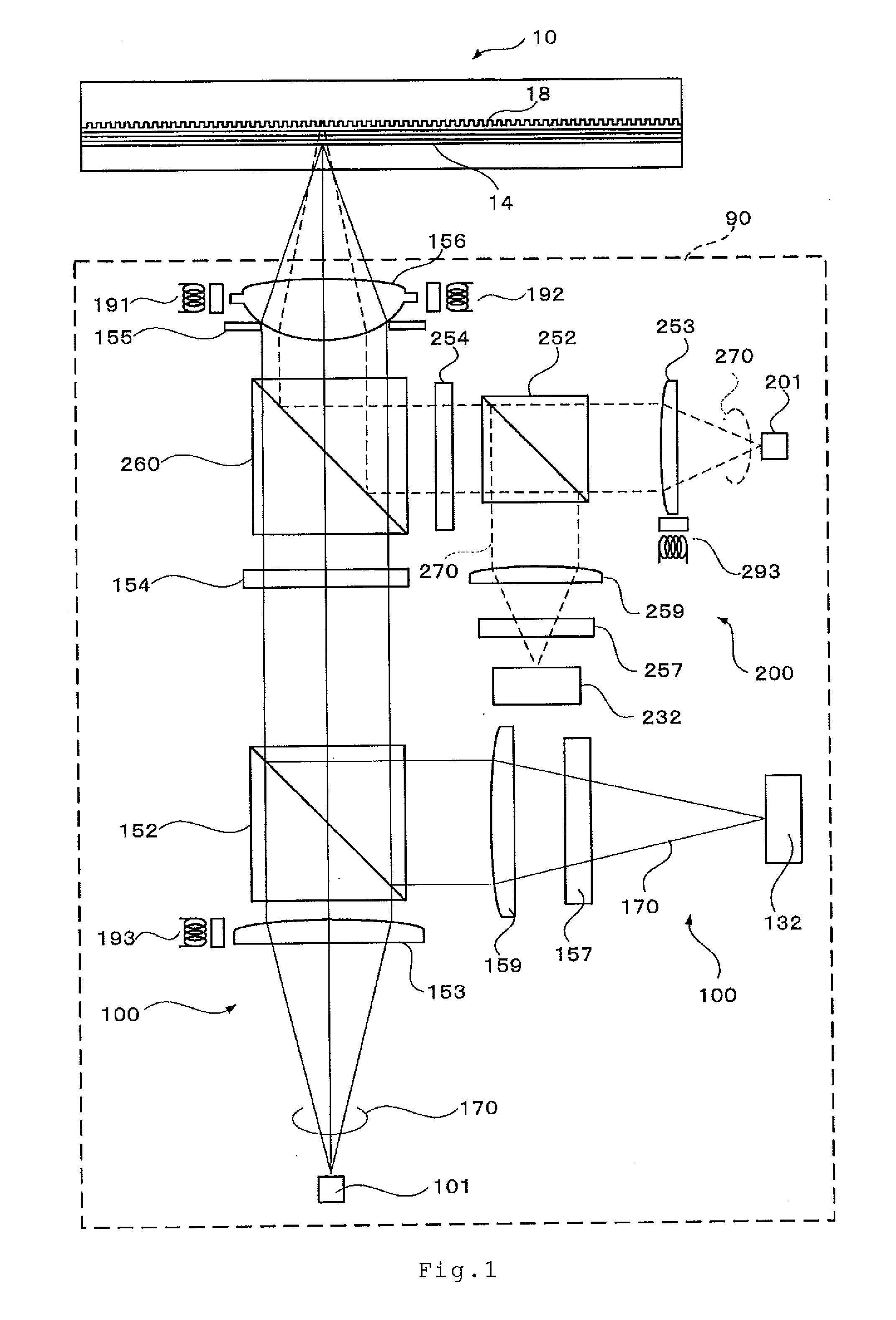
[0122]FIG. 1 shows an optical recording medium 10 according to the present invention and a configuration of an optical pickup 90 used for recording and reading in this optical recording medium 10. The optical pickup 90 includes a first optical system 100 and a second optical system 200. The first optical system 100 denotes an optical system (i.e. recording and reading optical system) that performs recording / reading for a group of recording and reading layers 14 of the optical recording medium 10. The second optical system 200 denotes an optical system (i.e. tracking optical system) that performs tracking control using a servo layer 18 (described later) and a recorded area of the group of recording and reading layers 14 when recording information in the group of recording and reading layers 14 using the first optical system 100.

[0123]A divergent recording and reading beam 170 with a blue wavelength of 380 to 450 nm (405 nm in this case), which is emitted from a light source 101 of th...

second embodiment

[0189]A beam 270 which becomes a light source of a tracking optical system 20 in the optical pickup 90 has a red wavelength of 630 to 680 nm (650 nm, here). In the optical pickup 90 in the second embodiment, the wavelength is different between a first optical system 100 and a second optical system 200, and thus, beams 170 and 270 can be separated by a filter having wavelength dependence.

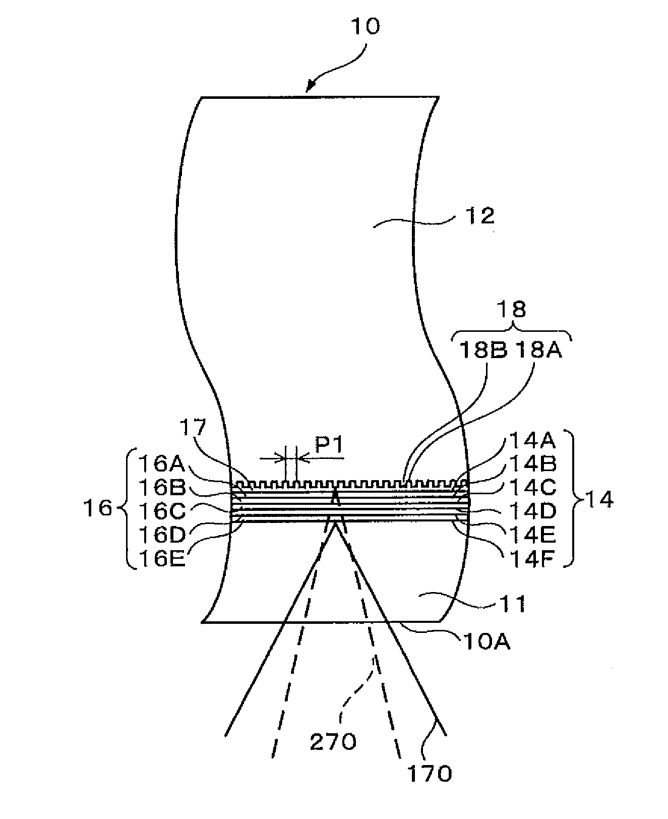
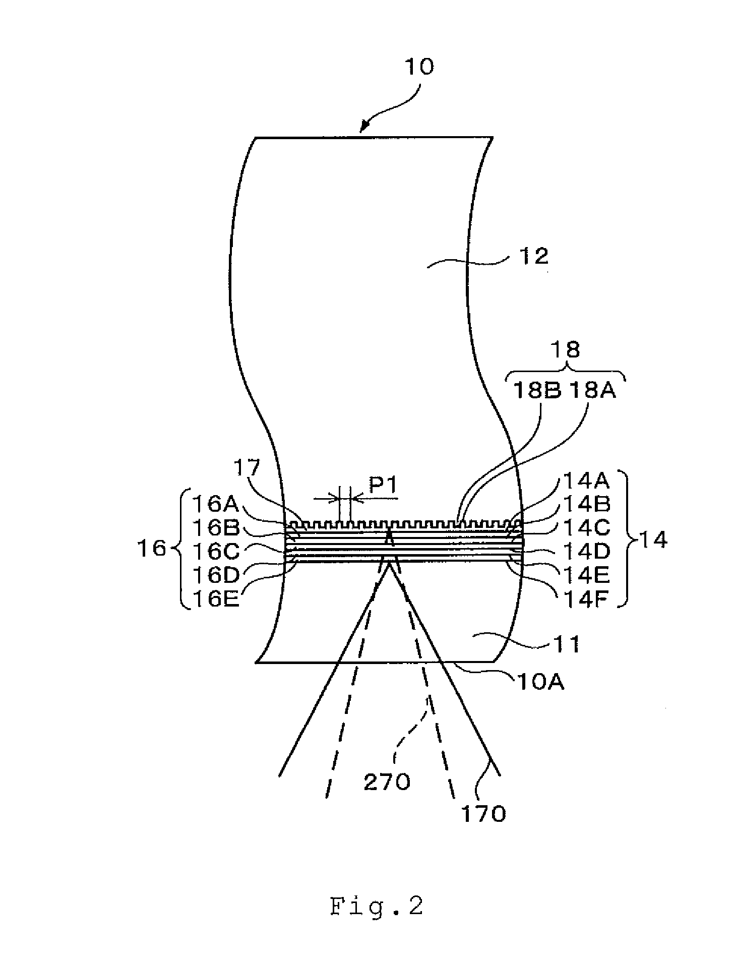
[0190]A servo layer 18 of the optical recording medium 10 is composed by forming a reflective layer on a concavo-convex pattern (lands and grooves) for tracking control of a support substrate 12. The recording and reading beam 170 is set such that an amount of reflected light when the recording and reading beam 170 is applied to a servo layer 18 becomes 5 times or less the amount of reflected light when the recording and reading beam 170 is applied to a group of recording and reading layers 14. As a result, when the recording and reading beam 170 is applied to the group of recording and reading layer...

fourth embodiment

[0247]As hereinbefore discussed, according to the optical recording medium 410 of the fourth embodiment, the servo layer 418 is formed on one surface of the support substrate 412, and the first group of recording and reading layers 414 and the second group of recording and reading layers 434 are disposed on both surfaces of the support substrate 412. As a result, because internal stress generated when the first and second groups of recording and reading layers 414 and 434 are formed is dispersed into both sides of the support substrate 412, warpage and deformation of the optical recording medium 410 can be prevented. Such dispersion of internal stress enables preventing warpage of the optical recording medium 410 even if a thickness of the support substrate 12 is set within the range of 10 to 1000 μm, and preferably, within the range of 10 to 600 μm.

[0248]At this time, an attempt to form concavo-convex patterns for tracking on both sides of the support substrate 412 complicates a pr...


PUM

PropertyMeasurementUnit
distanceaaaaaaaaaa
reflectanceaaaaaaaaaa
thicknessaaaaaaaaaa

Abstract

An optical recording medium includes a recording and reading layer that is previously staked or formed afterward and has no concavo-convex pattern for tracking control, and a servo layer in which a concavo-convex pattern or a groove for tracking control is formed. Information can be recorded in the recording and reading layer while tracking is performed using the servo layer.

Description

BACKGROUND OF THE INVENTION[0001]1. Field of the Invention[0002]The present invention relates to an optical recording medium including a plurality of recording and reading layers, an optical recording and reading method and an optical recording and reading apparatus that record information on the optical recording medium, and a method for producing the optical recording medium.[0003]2. Description of the Related Art[0004]Conventionally, optical recording media such as a CD-DA, a CD-ROM, a CD-R, a CD-RW, a DVD-ROM, a DVD-R, a DVD+ / −RW, a DVD-RAM and a Blu-ray Disc (BD) have been widely used for viewing digital moving image content or recording digital data. Among them, in the BD, which is regarded as one of next-generation DVD standards, a wavelength of laser light used for recording and reading is set to be short, that is, 405 nm, and a numerical aperture of an objective lens is set to 0.85. In an optical recording medium conforming to the BD standard, tracks are formed at a pitch o...

Claims


Application Information

Patent Timeline
Patent Type & Authority Applications(United States)
IPC IPC(8): G11B7/00B21D39/03G11B7/24
CPCG11B7/09G11B7/1267G11B7/14G11B7/24018Y10T29/49826G11B7/24038G11B7/2405G11B7/24079G11B7/0903G11B7/2403
Inventor INOUE, MOTOHIROUSHIDA, TOMOKIKOSUDA, ATSUKOKIKUKAWA, TAKASHI
Owner TDK CORPARATION
Why Eureka
Try Eureka