
Light emitting device having surface-modified silicate luminophores

a technology of luminophores and luminophores, which is applied in the direction of energy-saving lighting, transportation and packaging, and sustainable buildings, etc., can solve the problems of low radiation stability, high sensitivity of luminophores to water, air humidity, and other environmental factors, and achieves improved radiation stability, improved operational life, and moisture stability

Active Publication Date: 2012-08-16
LITEC GBR +1
View PDF9 Cites 8 Cited by
  • Summary
  • Abstract
  • Description
  • Claims
  • Application Information

AI Technical Summary

Benefits of technology

The present invention provides light emitting devices that use silicate luminophores that are stable to moisture, radiation, and other environmental influences, and have a longer operational lifetime. The devices also use luminophores that have been surface-treated with fluorinated agents, which improve their performance. The invention also includes the ability to detect and fix fine particles of fluorides or fluorine compounds on the luminophore surface, making them hydrophobic and curing surface defects. Overall, the invention provides improved performance and stability of light emitting devices.

Problems solved by technology

However, the luminophores based on the alkaline earth metal silicates also have various disadvantageous properties.
Some of the disadvantages include a comparatively low radiation stability and high sensitivity of the luminophores to water, air humidity, and other environmental factors.
For some of the current applications of wavelength-conversion luminophores, these properties may be problematic.
However, in relation to silicatic luminophores, the protection achievable may be insufficient to improve the lifetime of corresponding LED lamps to the desired degree.
Furthermore, in the case of coated luminophores, it may be necessary to accept losses in brightness, shifts in the color location, and other quality losses.
Processes for microencapsulation of the luminophore particles by means of gas phase processes may be inconvenient and costly.

Method used


Image

  • Light emitting device having surface-modified silicate luminophores
  • Light emitting device having surface-modified silicate luminophores
  • Light emitting device having surface-modified silicate luminophores

Examples


working example a1

[0069]Working Example A1 describes the preparation of a luminophore provided with a fluorinated surface layer and having the base lattice composition Sr2.9Ba0.01Ca0.05SiO5:Eu0.04 according to an exemplary embodiment of the present invention, which is described as sample F-103 together with its optical data in Table 1, and the emission spectrum that is designated as “3” in FIG. 1a.

[0070]Table 1 contains optical and moisture stability data of europium-activated strontium oxyorthosilicate luminophore samples which have been treated with different amounts of NH4F. To synthesize the corresponding luminophore matrix, the stoichiometric amounts of SrCO3, BaCO3, CaCO3, Eu2O3, and SiO2 and 0.2 mol of NH4Cl are mixed vigorously and then subjected, in corundum crucibles, to a 5-hour calcination process at 1400° C. in an N2 / H2 atmosphere containing 2% hydrogen. After the calcination process has ended, the calcinated material is homogenized, ground and washed with H2O. Subsequently, 100 g of th...

working example a2

[0071]To prepare the luminophore containing sample F-202 according to an exemplary embodiment of the present invention, the optical data of which are specified in Table 2 and the emission spectrum of which is designated as “4” in FIG. 6a, 100 g of the luminophore matrix described in Working Example A1 are mixed with 2.474 g of NH4HF2. Table 2 contains optical and moisture stability data of europium-activated strontium oxyorthcsilicate luminophore samples which have been treated with different amounts of NH4HF2. In this case, the fluorinated surface layer is applied by wet-chemical precipitation by taking the mixture in 1 L of deionized water and 400 g of glass beads on a roll mill. Treatment for one hour is followed by the removal of the coated luminophore from the solution and an after-treatment analogous to Working Example A1.

working example a3

[0072]Here, 30 g of the luminophore produced according to Working Example A2 are heat treated in a corundum crucible at 400° C. in an N2 / H2 atmosphere containing 35% hydrogen for 60 minutes. After cooling, the sample F-202T, the optical data of which are specified in Table 2 and the emission spectrum of which is designated as “5” in FIG. 6a, is homogenized by screening to produce an exemplary embodiment of the present invention.


PUM


Abstract

Exemplary embodiments of the present invention relate to a light emitting device including a light emitting diode and a surface-modified luminophore. The surface-modified luminophore includes a silicate luminophore and a fluorinated coating arranged on the silicate luminophore.

Description

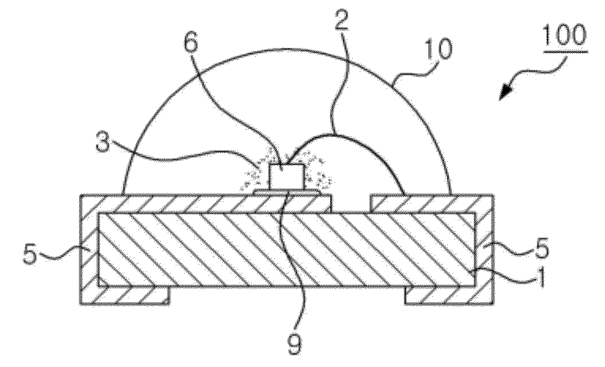
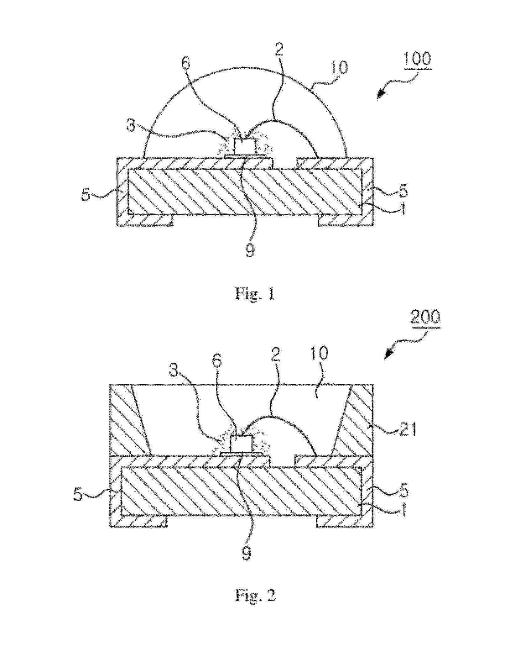
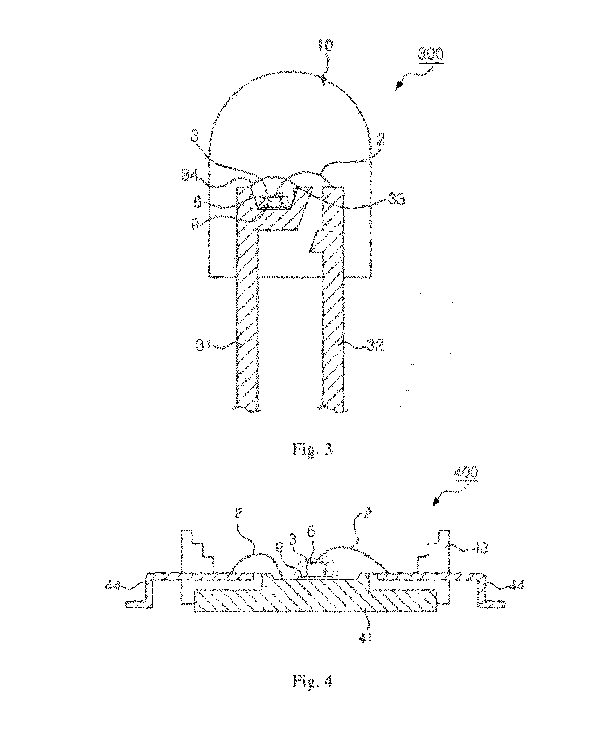
CROSS REFERENCE TO RELATED APPLICATIONS[0001]This application claims priority from and the benefit of German Patent Application No. 10 2010 034 322.6, filed on Aug. 14, 2010, and Korean Patent Application No. 2010-0137026, filed on Dec. 28, 2010, which are all hereby incorporated by reference for all purposes as if fully set forth herein.BACKGROUND OF THE INVENTION[0002]1. Field of the Invention[0003]Exemplary embodiments of the present invention relate to light emitting devices having inorganic luminophores based on doped alkaline earth metal silicate compounds which are capable of converting high-energy primary radiation, i.e., for example, ultraviolet (UV) radiation or blue light, to a longer-wavelength secondary radiation within the visible spectral region, which can be used as radiation converters in light-emitting devices such as color or white-light emitting light emitting diodes (LEDs). Exemplary embodiments of the present invention also relate to light emitting devices havi...

Claims


Application Information

Patent Timeline
Patent Type & Authority Applications(United States)
IPC IPC(8): H01L33/48
CPCC09K11/7734H01L33/502H01L33/501C09K11/025H01L2224/48091H01L2224/48247H01L2224/8592H01L2924/19107H01L2924/181H01L2224/73265Y10T428/2991Y10T428/2993Y10T428/2998Y02B20/00C09K11/77342H01L2924/00014H01L2924/00012H01L33/507H01L33/486H01L33/52H01L33/64H01L25/0753
Inventor LEE, CHUNG HOONTEWS, WALTERROTH, GUNDULASTARICK, DETLEF
Owner LITEC GBR
Learn More