Method for producing separator, method for producing molten salt battery, separator, and molten salt battery

a technology for molten salt batteries and separators, which is applied in the direction of cell components, final product manufacturing, sustainable manufacturing/processing, etc., can solve the problems of inability to easily adjust the electrical power generation amount in accordance, and achieve the effects of lowering the risk of short circuit, reducing internal resistance, and improving power

Active Publication Date: 2012-08-16
SUMITOMO ELECTRIC IND LTD
View PDF4 Cites 7 Cited by
  • Summary
  • Abstract
  • Description
  • Claims
  • Application Information

AI Technical Summary

Benefits of technology

[0035]In the present invention, the raw material of the separator of a molten salt battery is rendered a resin, whereby the molten salt battery produces advantageous effects including the following: the molten salt battery is lower in the

Problems solved by technology

When electric power is generated by use of a natural energy, the electric power generation amount is easily varied because of a change in natura

Method used


Image

  • Method for producing separator, method for producing molten salt battery, separator, and molten salt battery
  • Method for producing separator, method for producing molten salt battery, separator, and molten salt battery
  • Method for producing separator, method for producing molten salt battery, separator, and molten salt battery

Examples


embodiment 1

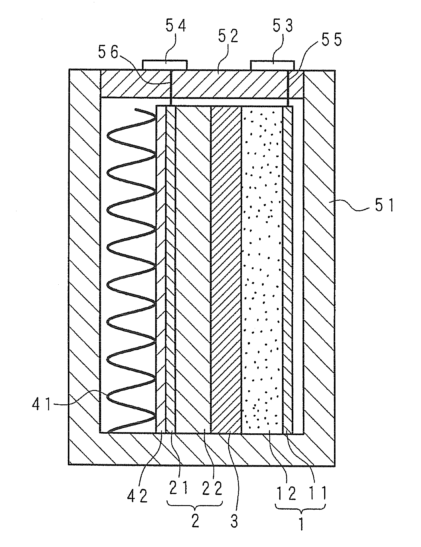
[0047]FIG. 1 is a schematic sectional view illustrating a structural example of a molten salt battery according to Embodiment 1 of the present invention. In FIG. 1, the illustrated schematic sectional view is one obtained by cutting the molten salt battery vertically. The molten salt battery has the following structure: inside a battery case 51 in the form of a rectangular parallelepiped box having an opened upper surface, a positive electrode 1 in the form of a rectangular plate, a separator 3 in a sheet form, and a negative electrode 2 in the form of a rectangular plate are arranged in parallel, and a lid section 52 is capped to the battery case 51. The battery case 51 and the lid section 52 are made of Al (aluminum). The positive electrode 1 and the negative electrode 2 are each made into a flat rectangular plate form, and the separator 3 is made into a sheet form. The separator 3 is interposed between the positive electrode 1 and the negative electrode 2. The positive electrode ...

embodiment 2

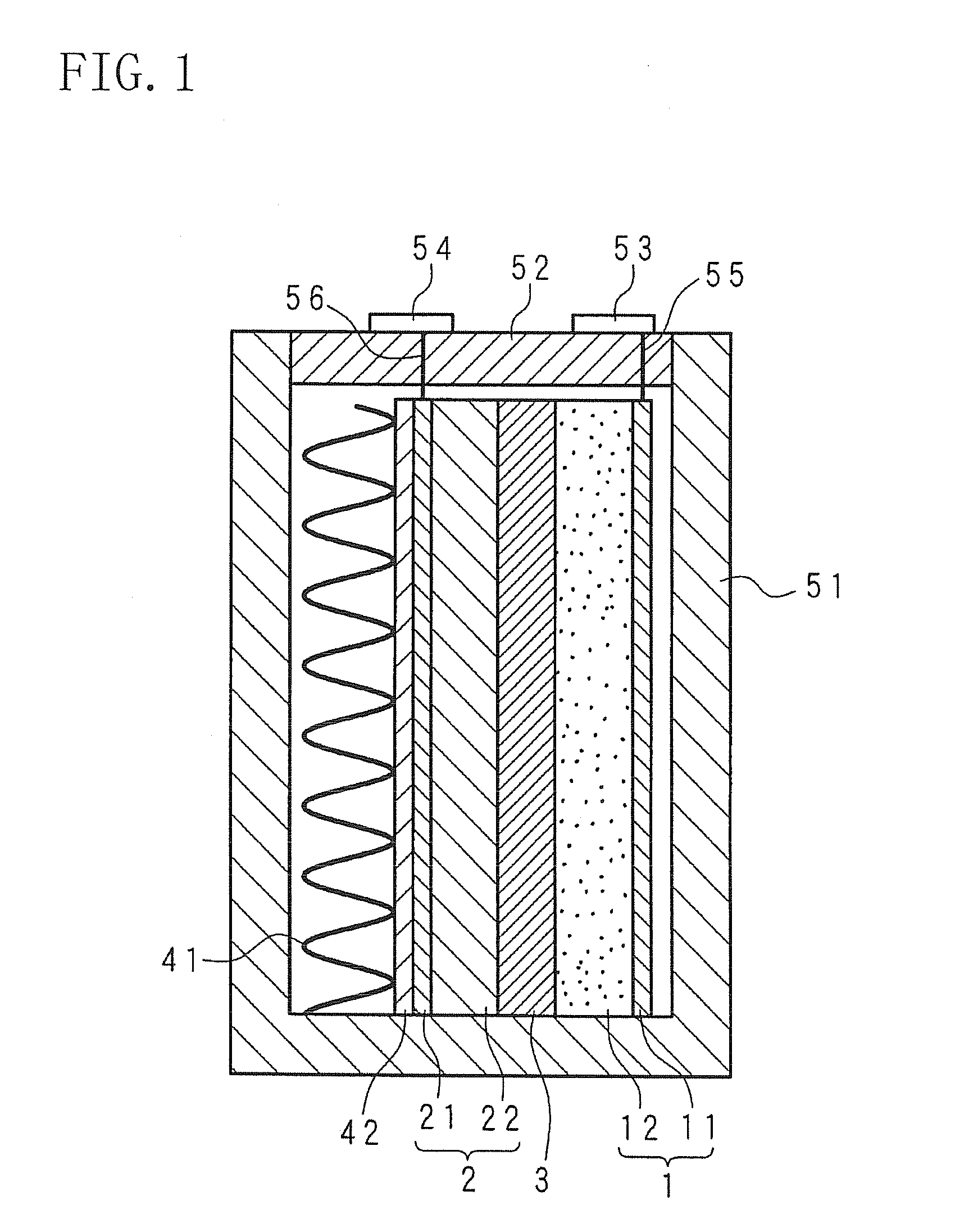
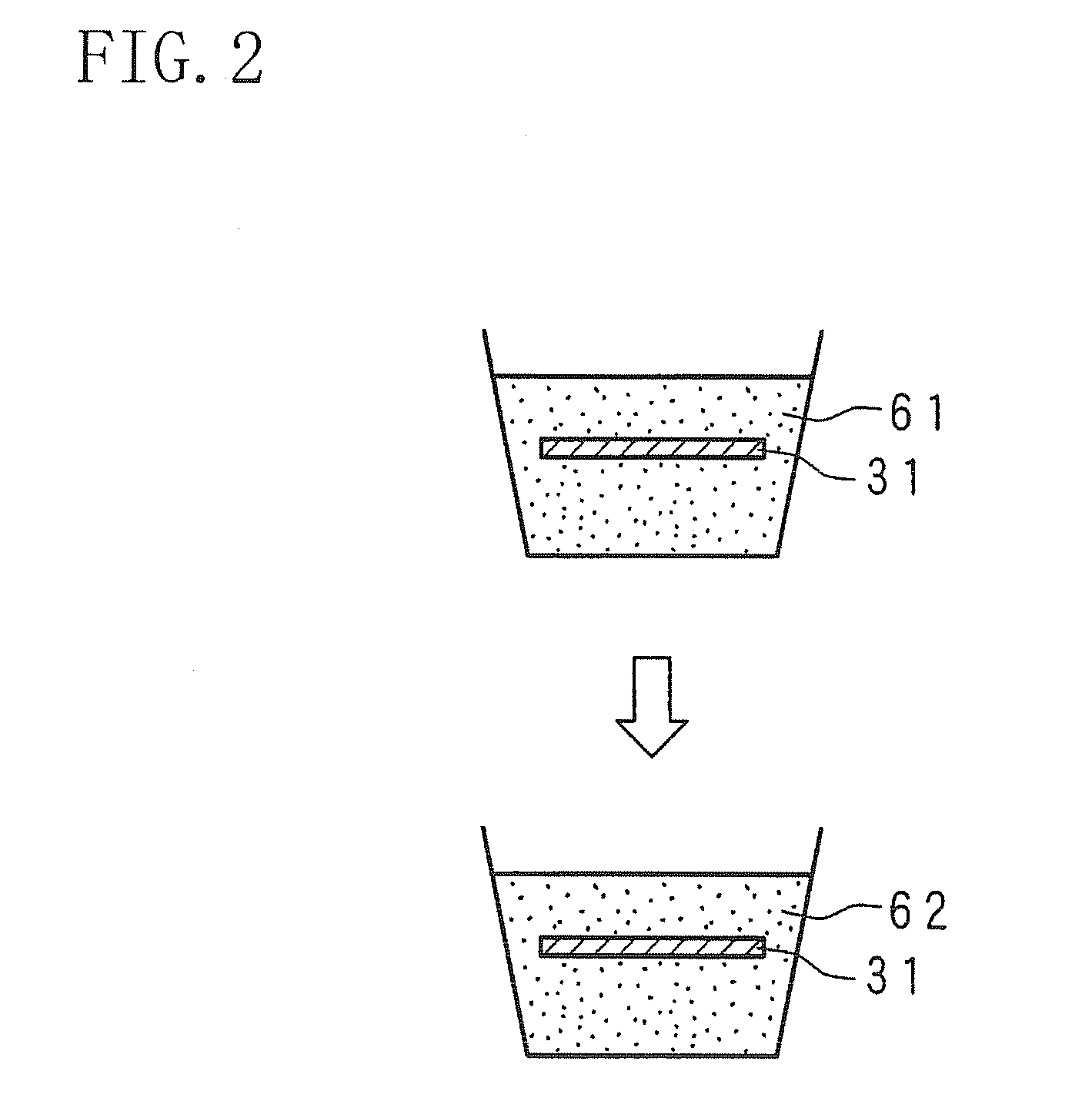
[0074]FIG. 9 is a schematic sectional view of a structural example of a molten salt battery according to Embodiment 2 of the present invention. In FIG. 9, the illustrated schematic sectional view is one obtained by cutting the molten salt battery vertically. In the same manner as in Embodiment 1, a separator 3 is a porous resin sheet, such as a PTFE sheet 31 to which hydrophilicity is given, and is made into a bag form. Specifically, resin sheets to which hydrophilicity is given are put onto each other, and circumferential edges of the resin sheets are joined to each other except the edges of respective single sides of the sheets, thereby producing the bag-form separator 3. For example, two PTFE sheets 31 each having hydrophilicity given by UV radiation are put onto each other, and then their circumferential edges are heated to be melted and bonded to each other, thereby producing the separator 3. A positive electrode 1 is wrapped in the bag-form separator 3 to be present in the bag...

embodiment 3

[0077]FIG. 10 is a schematic sectional view of a structural example of a molten salt battery according to Embodiment 3 of the present invention. In FIG. 10, the illustrated schematic sectional view is one obtained by cutting the molten salt battery vertically. The molten salt battery has positive electrodes 1 and negative electrodes 2. The positive electrodes 1 are each formed by painting a positive electrode material 12 containing a positive electrode active material onto both surfaces of a rectangular plate-form current collector 11 of the positive electrode. The negative electrodes 2 are each formed by depositing a negative electrode material 22 containing a negative electrode active material onto both surfaces of a rectangular plate-form current collector 21 of the negative electrode by plating. The plural positive electrodes 1 and the plural negative electrodes 2 are each formed into the form of a flat rectangular plate, and are alternately arranged in a battery case 51, in the...


PUM

PropertyMeasurementUnit
Pressureaaaaaaaaaa
Percent by atomaaaaaaaaaa

Abstract

A separator of a molten salt battery made of a porous resin sheet. The separator is improved in wettability to a molten salt by giving hydrophilicity to the resin sheet. In the case of a fluororesin sheet, the sheet is impregnated with water, and irradiated with ultraviolet rays so that C—F bonds in the fluororesin are cleaved and the resultant reacts with water to generate hydrophilic groups, such as OH groups, in each surface layer thereof. The separator gains hydrophilicity through the hydrophilic groups. The separator made of the resin can be made into a bag form. In a molten salt battery having the bag-form separator, the growth of a dendrite is prevented.

Description

TECHNICAL FIELD[0001]The present invention relates to a molten salt battery using a molten salt as an electrolyte, and particularly to a method for producing a separator having endurance, a method for producing a molten salt battery, a separator, and a molten salt battery.BACKGROUND ART[0002]In recent years, the use of natural energies of sunlight, wind power, and others has been advanced. When electric power is generated by use of a natural energy, the electric power generation amount is easily varied because of a change in natural conditions, such as weather, and further the electric power generation amount is not easily adjusted in accordance with electric power demand. Accordingly, in order to supply the electric power generated by use of a natural energy, it is necessary to level the supply power by charging and discharging through the use of a storage battery. In order to attain further promotion of the use of natural energies, storage batteries high in energy density and effi...

Claims


Application Information

Patent Timeline
IPC IPC(8): H01M2/16B05D5/12B05D3/06H01M10/04H01M50/403H01M50/417H01M50/426H01M50/466
CPCY02E60/122H01M2300/0048H01M2/18H01M10/0569Y10T29/49115H01M10/0525H01M10/0568H01M2/1653H01M2/145Y02E60/10H01M50/403Y02P70/50H01M50/417H01M50/466H01M50/426H01M50/489H01M50/491H01M50/414H01M50/449H01M50/463H01M50/46H01M10/399
Inventor FUKUNAGA, ATSUSHISAKAI, SHOICHIROHIRAIWA, CHIHIRONITTA, KOJIMAJIMA, MASATOSHIINAZAWA, SHINJI
Owner SUMITOMO ELECTRIC IND LTD
Why Eureka
Try Eureka