Hybrid power source system

Active Publication Date: 2012-08-30
MURATA MFG CO LTD
View PDF4 Cites 7 Cited by
  • Summary
  • Abstract
  • Description
  • Claims
  • Application Information

AI Technical Summary

Benefits of technology

[0046]In the hybrid power source system of the present invention, the generated electric power which the solar cell module or the fuel cell module generates is supplied to each of the load and the secondary cell connected in parallel with each other. Also, when the generated electric power exceeds the electric power with which the load is driven, the secondary cell is charged in such a way that the surplus electric power is stored in the secondary cell. On the other hand, when the generated electric power falls below the electric power with which the load is driven, the secondary cell is discharged, and the load is driven by either the solar cell module or the fuel cell module and the secondary cell. As a result, there is no necessity for the solar cell module or the fuel cell module to respond to the maximum power consumption of the load, and it is only necessary to supply the power consumption of the load on the average. Therefore, it is possible to miniaturize the size of the solar cell module or the fuel cell module.
[0047]In this case, the hybrid power source system of the present invention, as a feature thereof, has the direct-current voltage converting means to supply a suitable voltage to the load and the secondary cell after the generated electric power is converted into the suitable voltage. As a result, the loss when the secondary cell is charged can be suppressed to the minimum. In addition, when the secondary cell is discharged, it is poss

Problems solved by technology

As a result, there is caused a problem that the t

Method used


Image

  • Hybrid power source system
  • Hybrid power source system
  • Hybrid power source system

Examples


embodiment 1

[0065]In Embodiment 1, an example of a hybrid power source system described in claims 1, 2, 4, and 5 will be mainly described.

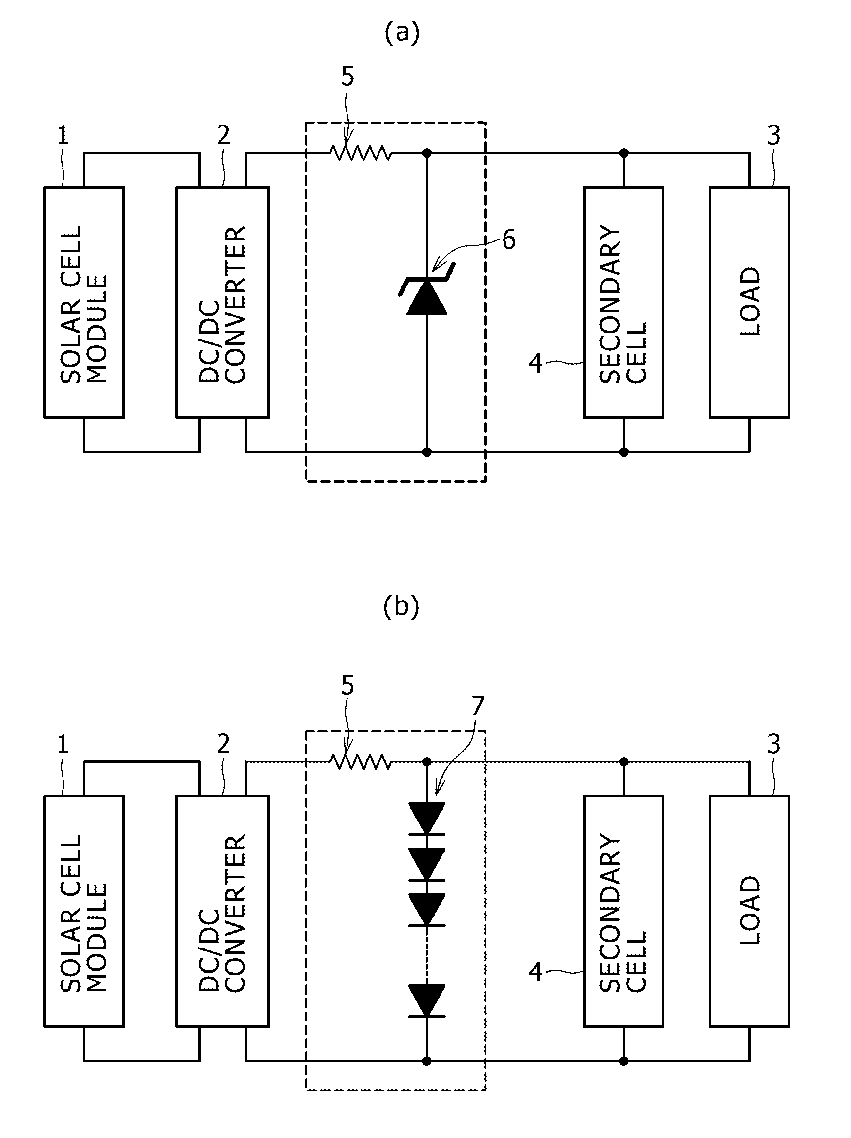
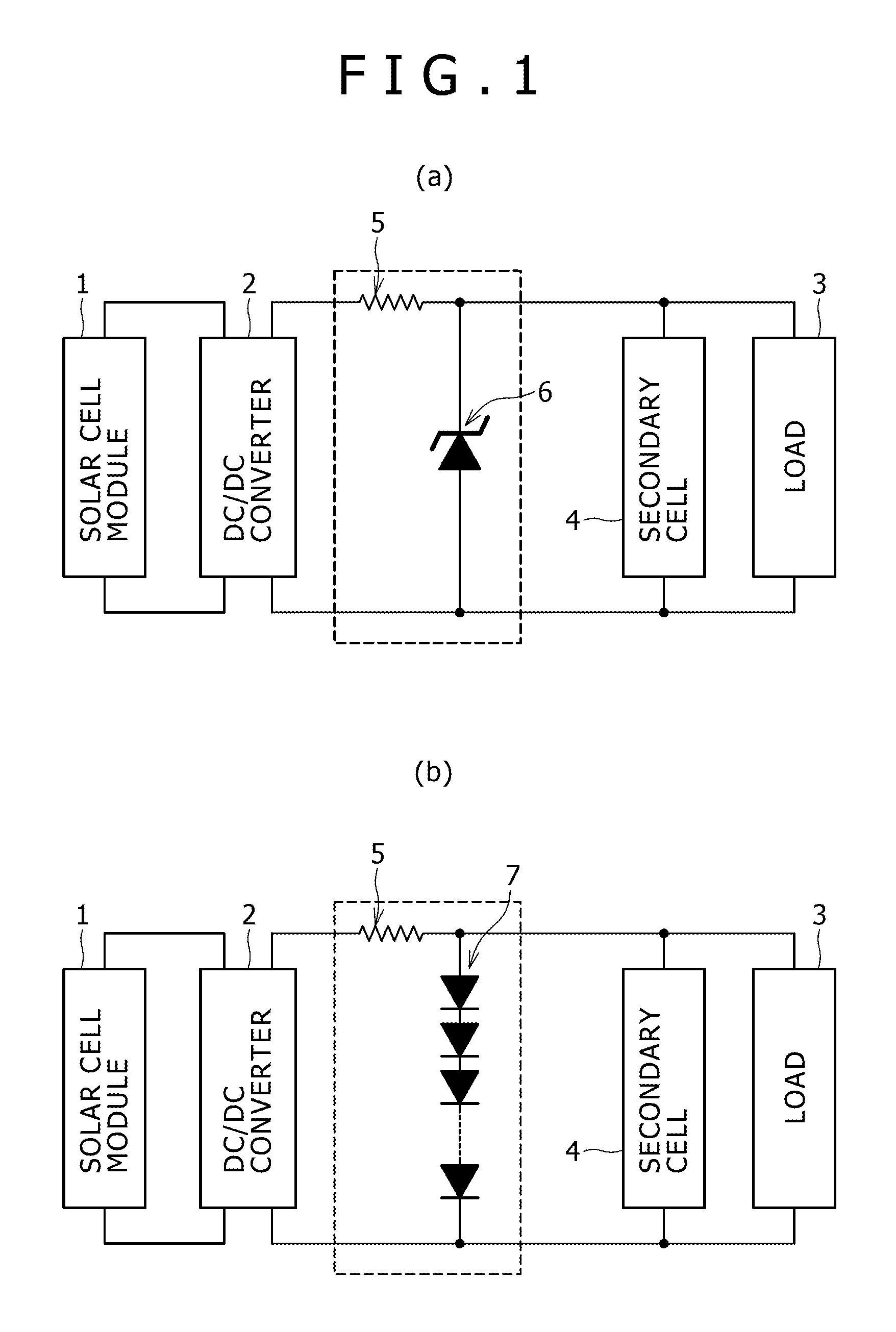
[0066]FIG. 1(a) is a schematic diagram showing a configuration of a hybrid power source system 10 based on Embodiment 1. The hybrid power source system 10 is composed of a solar cell module 1, a DC / DC converter 2 as the direct-current voltage converting means described above, a secondary cell 4, a resistor 5, and a constant voltage diode 6, and the solar cell module 1 is connected to an input side of the DC / DC converter 2 and a load 3 and the secondary cell 4 are connected in parallel with each other on an output side of the DC / DC converter 2.

[0067]In the hybrid power source system 10, after an electric power which the solar cell module 1 generates is converted into a suitable voltage by the DC / DC converter 2, the resulting suitable voltage is supplied to the load 3 and the secondary cell 4. Also, when the generated electric power exceeds an electric power wi...

embodiment 2

[0076]In Embodiment 2, an example of a hybrid power source system described in claims 6 and 7 will be mainly described.

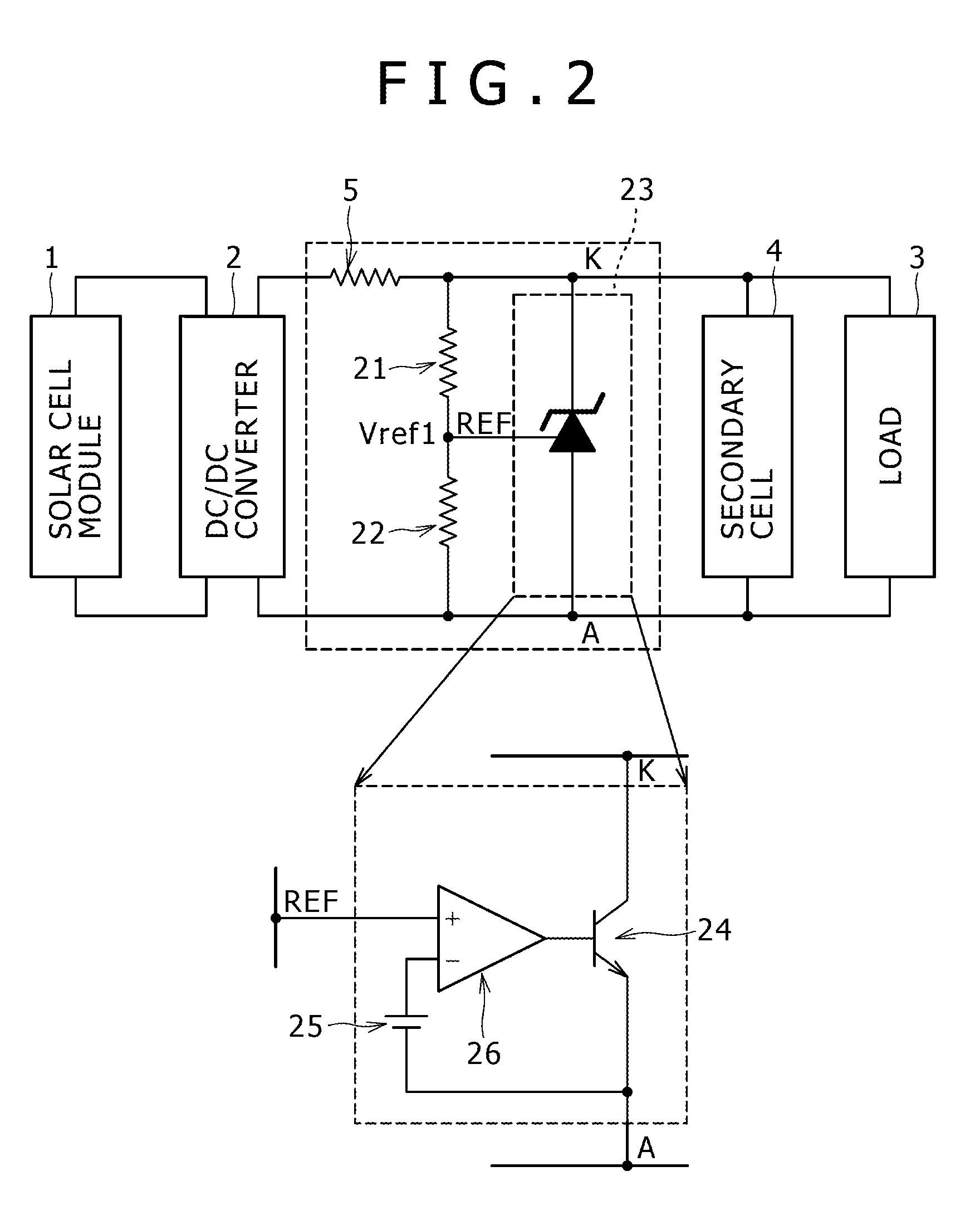
[0077]FIG. 2 is a schematic diagram showing a configuration of a hybrid power source system 20 based on Embodiment 2. The hybrid power source system 20 is composed of a solar cell module 1, a DC / DC converter 2 as the direct-current voltage converting means described above, a secondary cell 4, a resistor 5, division resistors 21 and 22, and a shunt regulator circuit 23. In the hybrid power source system 20, the shunt regulator circuit 23 is used as the shunt circuit described above instead of the constant voltage diode 6, and the division resistors 21 and 22 are provided. Since portions other than those are the same as those in the hybrid power source system 10, points of difference will be mainly described.

[0078]The shunt regulator circuit 23, as shown in an enlarged diagram, is composed of a shunt path composed of a transistor 24 connected in parallel with the seco...

embodiment 3

[0086]In Embodiment 3, an example of a hybrid power source system described in claim 3 will be mainly described.

[0087]FIG. 3(a) is a schematic diagram showing a configuration of a hybrid power source system 30 based on Embodiment 3 of the present invention. The hybrid power source system 30 is composed of a solar cell module 1, a DC / DC converter 31 as the direct-current voltage converting means described above, a secondary cell 4, division resistors 21 and 22, and a shunt regulator circuit 23. In the hybrid power source system 30, the DC / DC converter 31 is used instead of the DC / DC converter 2 used in each of the hybrid power source systems 10 and 20, and the resistor 5 is omitted. Since portions other than those are the same as those in the hybrid power source system 20, points of difference will be mainly described.

[0088]As previously stated, the output voltage from the DC / DC converter 2 is set slightly higher than the voltage of the secondary cell 4. In this case, although some c...


PUM


Abstract

To provide a hybrid power source system in which either a solar cell or a fuel cell and a secondary cell are combined with each other, and the secondary cell is used as an electric power buffer and which can maintain a high energy efficiency even when there is a change in a charging state of the secondary cell, a change in an operating condition, or a secular change in a member, prevent overcharging of the secondary cell, and suppress thermal deterioration of the solar cell or the fuel cell due to generation of a surplus electric power unable to be taken out. A hybrid power source system is composed of a solar cell module 1 or a fuel cell module, a DC/DC converter (2) which supplies a suitable voltage to a load (3) and a secondary cell (4) after converting an electric power generated by the module into the suitable voltage, the secondary cell (4), and a shunt circuit (a constant voltage diode (6) or a shunt regulator IC) which is connected in parallel with the secondary cell (4), and which, when the secondary cell (4) is substantially in a full charging state, transforms substantially all of a surplus electric power which is not consumed in the load (3), of the generated electric power, into heat to abandon the resulting heat.

Description

TECHNICAL FIELD[0001]The present invention relates to a hybrid power source system of either a solar cell or a fuel cell, and a secondary cell such as a lithium-ion cell.BACKGROUND ART[0002]An electric-generating capacity which a solar cell can generate is determined depending on an irradiance level of a light and, for example, the electric-generating capacity when there is no irradiation of the light is zero. On the other hand, an electric power corresponding to an operation state of an electronic apparatus is required for a power source for driving the electronic apparatus irrespective of the irradiance level of the light. Therefore, it is obvious that the power source for stably driving the electronic apparatus cannot be composed of only the solar cell.[0003]A hybrid power source system in which a solar cell and a secondary cell are combined with each other, and the secondary cell is used as an electric power buffer is known as a system in which a power source for stably driving ...

Claims


Application Information

Patent Timeline
IPC IPC(8): H01M12/08H01M2/00
CPCH01M14/005H01M16/00H01M16/006H02J7/35H02S40/38Y02E10/542Y02E10/566Y02E60/523Y02E60/122H02S40/00Y02E10/56Y02E60/10Y02E60/50Y02E70/30
Inventor SHIMURA, JUSUKEINOUE, YOSHIAKI
Owner MURATA MFG CO LTD
Why Eureka
Try Eureka