System and method for drilling a subsea well

a well control system and system technology, applied in the field of oil and gas exploitation, can solve the problems of reducing drilling speed, reducing drilling efficiency, and reducing drilling speed, so as to achieve softer and more dynamic process, high differential pressure capacity of the subsea pump system, and high drilling efficiency.

Active Publication Date: 2012-09-13
ENHANCED DRILLING
View PDF4 Cites 54 Cited by
  • Summary
  • Abstract
  • Description
  • Claims
  • Application Information

AI Technical Summary

Benefits of technology

[0024]A riser joint used may be particularly designed to function as a separator where the separated gas is vented to the surface via the riser and the liquid is pumped to the surface via an exterior return path from the main drilling riser (FIG. 2 and FIG. 3). The main difference here with prior art is that the mud / liquid level in the riser is controlled and located at a considerable level below the sea level. In this fashion it is prevented that drilling fluids or liquids will be unloaded from the top of the riser if gas is being released into the base of the riser.
[0032]If and when using the Low Riser Return System in another embodiment of this invention, the upper annular preventer can be closed during a drill pipe connection to avoid fluid level adjustment in the riser where in this case, the fluid level in the choke line is used to control and regulate the annulus pressure in order to compensate for the equivalent circulating density (ECD) effect (time saving). This is also explained in WO2009 / 123476, belonging to the applicant. The downside of having the liquid separated from the gas close to seabed as opposed to higher up in the riser is the longer pump suction line needed in deep water and the higher differential pressure capacity of the subsea pump system.
[0033]Another feature of this arrangement is the possibility to control bottom hole pressure while drilling (lower annular open) and when circulation out a well kick (lower annular closed), by controlling the liquid mud level in the choke line (subsea choke fully open) (FIG. 6). In this case the upper annular could be substituted with a rotating BOP (RBOP or RCD) 19 where the mud pressure in the borehole annulus 1 is regulated by the liquid mud level in the choke line 51 (FIG. 6). The pressure in the BOP and or BOP extension is now a function of the liquid level 51 in the choke line and the gas / air pressure above. This gas can either be ventilated to atmospheric pressure or controlled and regulated by the surface choke 22. This will create a softer and more dynamic process than having the pump suction pressure (only liquid) directly controlling the wellbore pressure. When low compressibility liquid is contained in a closed loop system, it will create a very stiff system. Small changes will affect well bore pressure immediately, while a level control of drilling fluid, mud and / or seawater in the choke line will be a slower and more controllable process.
[0034]While drilling, this could set up a unique method of pressure control. An influx into the borehole between the open hole and drillstring could have a self regulating effect. An influx into the wellbore has a density higher than air in top of the choke line and for the case of example 8½″ hole and 6″ drill collars would have a capacity of minimum 17.8 litre per meter hole section. The capacity of most choke lines (3″-5) is between 4.56 litre per meter to 12.6 litre per meter. An influx of a certain magnitude would increase the level in the smaller capacity choke line to a higher level than the influx constitute in the openhole—drillstring annulus, hence an influx progressing would be stopped just by the higher hydrostatic pressure created by a higher liquid level 51 in the choke line 17.

Problems solved by technology

Drilling for oil and gas in deep waters or drilling through depleted reservoirs is a challenge due to the narrow margin between the pore pressure and fracture pressure.
Reducing this effect by reducing the circulating flow rate, will again reduces drilling speed and causes problems with transport of drill cuttings in the borehole.
The primary barrier is now no longer effective in controlling or containing the formation pore pressure.
If heavier than seawater drilling fluid is being used, this will result in a hydrostatic pressure drop in the well.
Riser margin is difficult to achieve, particular in deep waters.
Hence the formation strength would be exceeded and mud losses would occur.
It would no longer be possible to circulate and transport the drill cuttings out of the borehole and the drilling operation would have to stop.
If this heavy drilling mud was carried all the way back to the drilling rig, as the case would be in a conventional drilling operation, the hydrostatic pressure would exceed the formation strengths, and hence mud losses would occur.
It is not recommended practice to rotate the drillstring while a conventional annular BOP is closed during drilling due to excess wear on the rubber element.
Common for all these drilling systems is that the drilling fluid returning from the well cannot be returned through high pressure choke or kill lines in a conventional manner due to limited formation strength when the BOP is closed after an influx has occurred.
Due to the heavy mud weight required or used, this mud will be displaced out of the wellbore annulus ahead of the lighter influx, hence the formation strength cannot support to be hydraulically in contact with the surface installation when the annulus of the wellbore and the conduit (kill or / and choke lines) back to surface are filled with the heavy drilling fluid.
This effect will restrict the use of earlier systems or will put severe strain and requirement on the equipment and processes in a well control event.
In dual Gradient Drilling and riserless drilling, many types of Subsea Lift Pumps (SLP) can normally not handle a significant amount of gas from the well, as the case may be in a well control event for a gas kick.
If this return path of fluids from the well has to go directly into the pump, it will put severe strain on the pump system.
Secondly, the bottom hole pressure will be a direct function of the fluid head in the annulus, the dynamic pressure loss in the annulus and the pump suction pressure.
It will be extremely difficult to achieve a stable and controllable suction pressure on the pump when you will have slugs of high concentration hydrocarbon gas flowing directly into the pump system.
This put severe requirements on the pump system to handle internal pressures.
If such a system was used in a situation where dual gradient drilling technology was used, the pressure on the downstream of the adjustable choke could become too high due to the high mud weight used.
Also since the riser was initially full of drilling mud, gas introduced into the base of the riser at great water depth could introduce further problems since the riser have limited collapse and internal pressure ratings.

Method used


Image

  • System and method for drilling a subsea well
  • System and method for drilling a subsea well
  • System and method for drilling a subsea well

Examples


Embodiment Construction

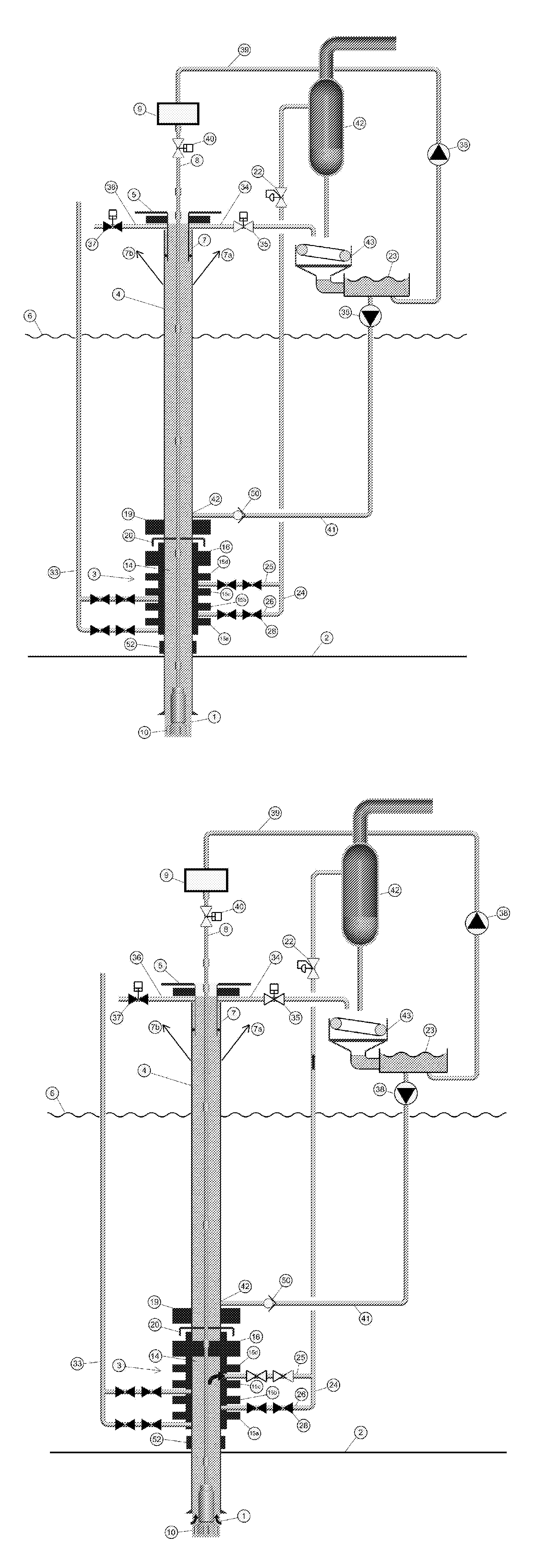
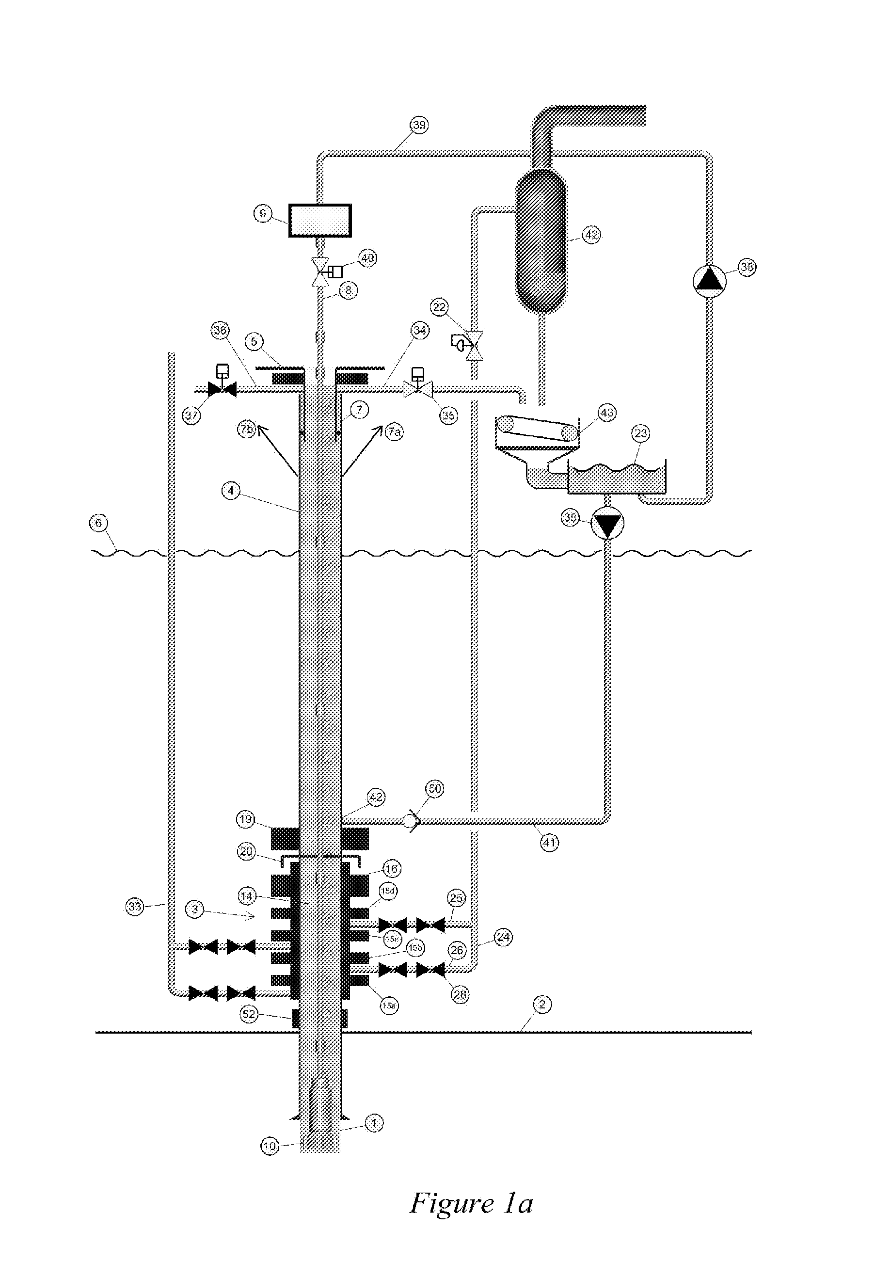
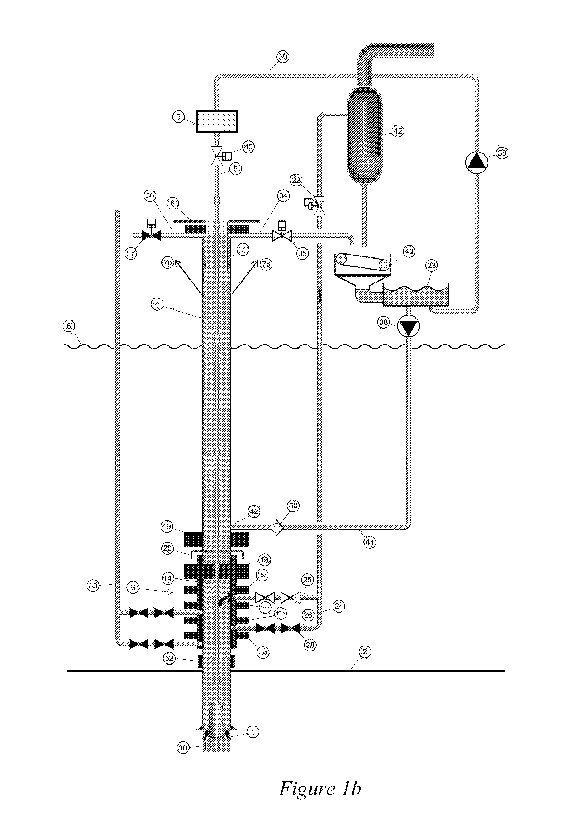
[0042]FIG. 2 illustrates a first embodiment of the subsea drilling system of the invention. It comprises a well having a well bore 1. The well bore may be partially cased. Above the seabed level 2 is arranged a subsea BOP 3 with a BOP extension joint 3a which is equipped with several pressure sensors and several inlets and outlets. A riser 4 is connected to the BOP and extends to a vessel 5 above the sea level 6. The riser 4 has a slip joint 7 to accommodating heave of the vessel 5 and a riser tensioning system 7a, 7b. Above the diverter housing and diverter outlet is a low pressure gas stripper installed 53 to prevent low pressure gas escaping to the drill floor of the drilling rig. The diverter line 36 is ventilated to the atmosphere or the mud gas separator (not shown). The flow line valve 35 is closed as the drilling fluid now is returned via the subsea pump 11 and return line 12.

[0043]Drill string 8 extends from a top drive 9 on the platform 5 and into the well bore 1. The lowe...


PUM


Abstract

A subsea mud pump can be used to return heavy drilling fluid to the surface. In order to provide a less stringent requirement for such a pump and to better manage the bottom hole pressure in the case of a gas kick or well control event, the gas should be separated from the drilling fluid before the drilling fluid enters the subsea mud pump and the pressure within the separating chamber. The mud pump suction should be controlled and kept equal or lower than the ambient seawater pressure. This can be achieved within the cavities of the subsea BOP by a system arrangement and methods explained. This function can be used with or without a drilling riser connecting the subsea BOP to a drilling unit above the body of water.

Description

TECHNICAL FIELD[0001]The present invention relates to the field of oil and gas exploitation, more specifically to systems and methods for well control, especially for well pressure control in wells with hydrocarbon fluids, as defined in the enclosed independent claims.BACKGROUND ART[0002]Drilling for oil and gas in deep waters or drilling through depleted reservoirs is a challenge due to the narrow margin between the pore pressure and fracture pressure. The narrow margin implies frequent installation of casing, and restricts the mud circulation due to pressure drop in the annulus between the wellbore and drill string or in other words the increase in applied or observed pressure in the borehole due to the drilling activity such as circulation of drilling fluid down the drill pipe up the annulus of the well bore. Reducing this effect by reducing the circulating flow rate, will again reduces drilling speed and causes problems with transport of drill cuttings in the borehole.[0003]Norm...

Claims


Application Information

Patent Timeline
Patent Type & Authority Applications(United States)
IPC IPC(8): E21B33/06
CPCE21B21/001E21B43/38E21B21/08
Inventor FOSSLI, BORRESANGESLAND, SIGBJORN
Owner ENHANCED DRILLING
Why Eureka
Try Eureka