Vehicle waste heat recovery device

a technology of waste heat recovery and vehicle, which is applied in the direction of machines/engines, soldering devices, auxilary welding devices, etc., can solve the problems of reduced density of working fluid, limited boiler performance, and limited mass flow rate of working fluid, so as to achieve the effect of reducing thermal efficiency

Inactive Publication Date: 2012-09-27
TOYOTA IND CORP
View PDF6 Cites 11 Cited by
  • Summary
  • Abstract
  • Description
  • Claims
  • Application Information

AI Technical Summary

Benefits of technology

[0007]The present invention has been designed to solve this problem, and an object thereof is to provide a vehicle waste heat recovery device employing a Rankine cycle with which reductions in thermal efficiency can be suppressed even when the ratio between the rotation speed of an engine and the amount of waste heat varies.

Problems solved by technology

However, the ratio between the rotation speed of the engine and the amount of waste heat from the engine, or in other words the amount of heat recovered by the boiler, is not typically fixed, and therefore, when the amount of heat recovered by the boiler is excessively large relative to the mass flow rate of the working fluid flowing into the boiler, for example, such that the temperature of the working fluid flowing out of the boiler increases, the density of the working fluid must be reduced by reducing the mass flow rate of the working fluid flowing through the boiler, or the amount of heat exchange performed in the boiler must be limited, in order to keep the pressure of the working fluid at or below the upper limit pressure.
As a result, the waste heat of the engine cannot be used effectively, and therefore the thermal efficiency of the Rankine cycle decreases.

Method used


Image

  • Vehicle waste heat recovery device
  • Vehicle waste heat recovery device
  • Vehicle waste heat recovery device

Examples


first embodiment

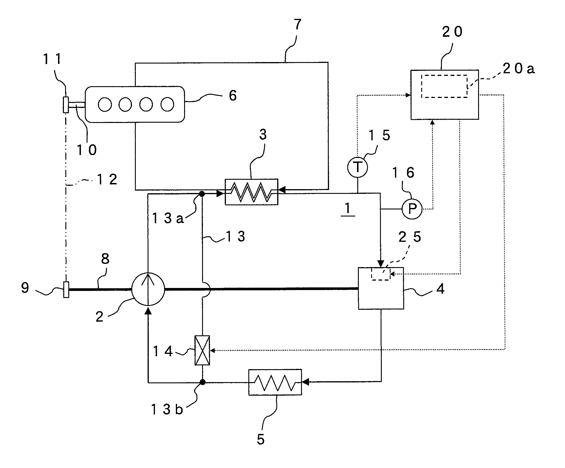
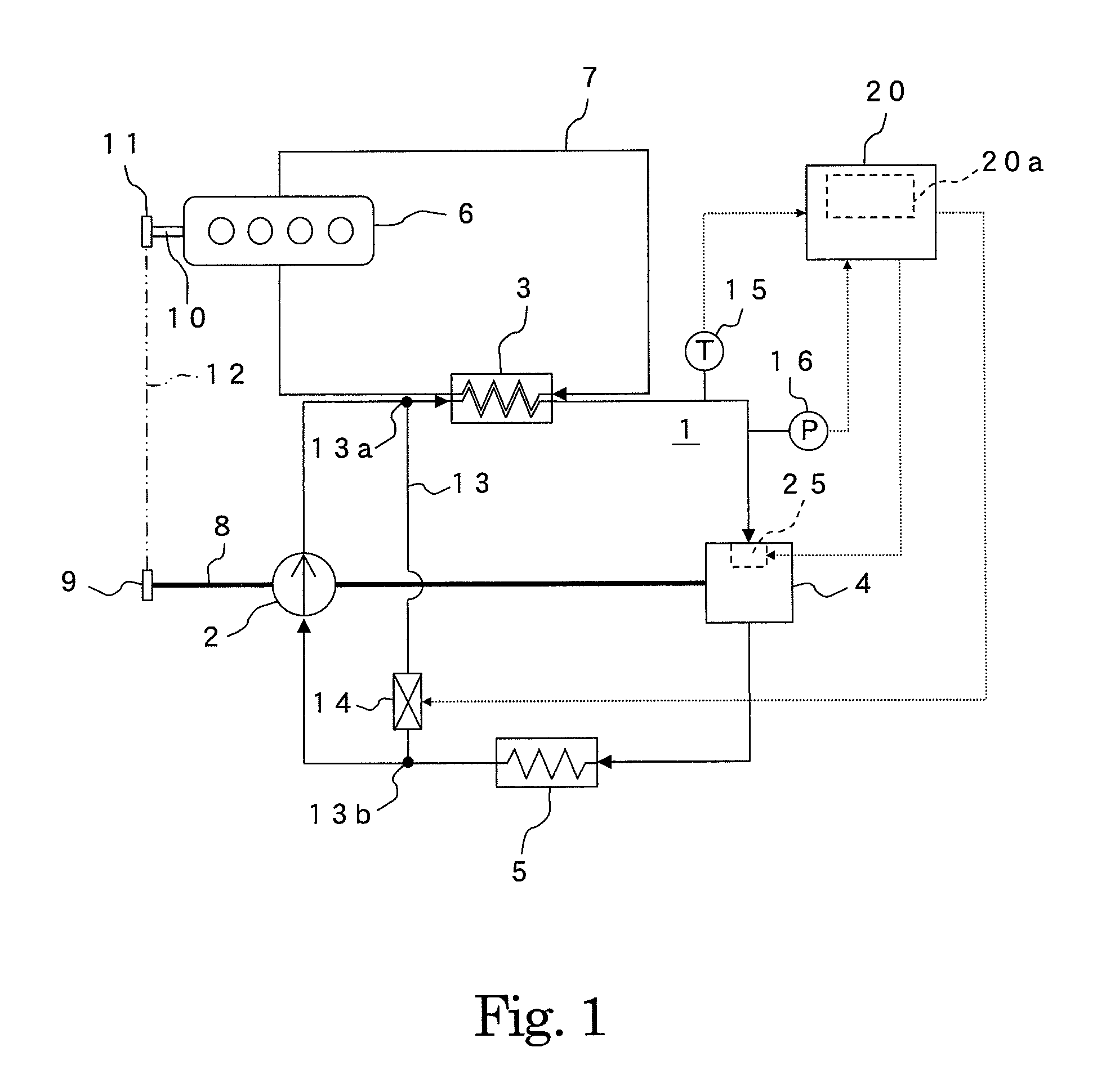
[0016]As shown in FIG. 1, a vehicle waste heat recovery device according to a first embodiment includes a Rankine cycle 1 constituted by a pump 2, a boiler 3, an expander 4 which is a scroll expander, and a condenser 5. The boiler 3 is a heat exchanger that absorbs waste heat from a vehicle, for example heat contained in cooling water 7 after cooling an engine 6, into a coolant (a working fluid) circulating through the Rankine cycle 1. The pump 2 and the expander 4 share a single drive shaft 8. A pulley 9 is provided on one end of the drive shaft 8, and a belt 12 is wrapped around the pulley 9 and a pulley 11 provided on a crankshaft 10 of the engine 6.

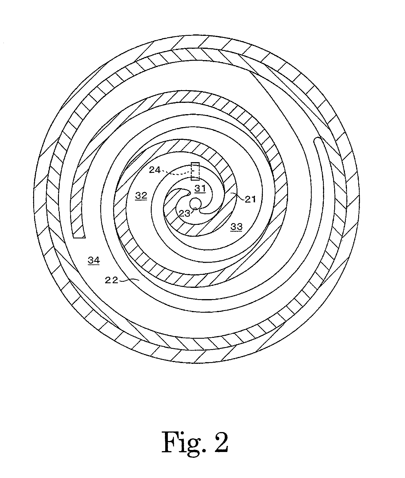
[0017]FIG. 2 shows an upper sectional view of an expansion mechanism portion of the expander 4. A spiral-shaped fixed scroll 21 is fixed within the expansion mechanism portion, and a turning scroll 22 is provided to be capable of turning relative to the fixed scroll 21 while meshed thereto. When the turning scroll 22 turns, the turnin...

second embodiment

[0027]Next, a vehicle waste heat recovery device according to a second embodiment of the present invention will be described. Note that in the following embodiments, identical symbols to the reference symbols used in FIGS. 1 to 3 indicate identical or similar constitutional elements, and detailed description of these elements has been omitted.

[0028]The vehicle waste heat recovery device according to the second embodiment of the present invention differs from that of the first embodiment in that only the expander 4 is coupled to the engine 6 to be capable of transmitting power thereto.

[0029]As shown in FIG. 4, the other end of the drive shaft 8 having the pulley 9 on one end is coupled to a rotary shaft, not shown in the drawing, of the expander 4. The pump 2 is driven by a motor 60. The motor 60 is electrically connected to the ECU 20. All other constitutions are identical to the first embodiment, except that the bypass passage 13 and the flow control valve 14 (see FIG. 1) of the fi...

third embodiment

[0031]Next, a vehicle waste heat recovery device according to a third embodiment of the present invention will be described.

[0032]The vehicle waste heat recovery device according to the third embodiment of the present invention differs from that of the first embodiment in the form of the intake volume varying assembly.

[0033]As shown in FIG. 5A, in the sub-port 24, a fixed plate 41 is fixed to an end portion on side opposite the side on which the respective expansion spaces exist, and one end of a spring 42 is connected to the fixed plate 41. A spool 43 is connected to another end of the spring 42. When the spool 43 is brought into contact with the turning scroll 22 by an elastic force of the spring 42, the expansion space 31 and the expansion space 32 separate. The elastic force of the spring 42 is adjusted such that when the set pressure P1 serving as a threshold having a smaller value than the upper limit pressure P0 acts on the spool 43, the spring 42 is compressed. All other con...


PUM


Abstract

When a detection value of a temperature sensor exceeds a set temperature, an ECU increases an opening of a sub-port by controlling a solenoid valve, and as a result, an intake volume of an expander increases. The ECU then adjusts the mass flow rate of a coolant flowing through a boiler so that a detection value of a pressure sensor indicates a pressure as close as possible to an upper limit pressure, on condition that an upper limit temperature is not exceeded.

Description

BACKGROUND OF THE INVENTION[0001]1. Field of the Invention[0002]The present invention relates to a vehicle waste heat recovery device, and more particularly to a vehicle waste heat recovery device employing a Rankine cycle.[0003]2. Description of the Related Art[0004]In response to calls from society for reductions in the amount of discharged carbon dioxide (CO2), there is a need for improvements in the fuel efficiency of vehicles having an engine, such as automobiles, and therefore techniques for making effective use of energy generated by the vehicle that would simply be discharged conventionally are currently being developed. For example, a waste heat utilization device employing a Rankine cycle to convert heat discharged from the engine, such as the heat of cooling water and the heat of exhaust gas, into power for a power generator and so on is available. The Rankine cycle is constituted by a boiler that generates superheated steam by isobarically heating a liquid phase fluid se...

Claims


Application Information

Patent Timeline
Patent Type & Authority Applications(United States)
IPC IPC(8): F01K23/10
CPCF02G5/00F01K23/065F01K13/02Y02T10/166Y02T10/12B23K37/0426B25B11/02B63B2221/02
Inventor MORI, HIDEFUMIIGUCHI, MASAOENOKIJIMA, FUMINOBU
Owner TOYOTA IND CORP
Why Eureka
Try Eureka