

Apparatus for producing laminated body
a technology of laminated bodies and apparatus, which is applied in the direction of vacuum evaporation coating, chemical vapor deposition coating, coating, etc., can solve the problems of increased cost, difficulty in maintaining the desired vapor pressure of each monomer vapor, and difficulty in controlling the heating temperature of the material monomer in the evaporation source, so as to achieve the lowest possible cost and produce stably and easily and effectively. a laminated body
- Summary
- Abstract
- Description
- Claims
- Application Information
AI Technical Summary
Benefits of technology
Problems solved by technology
Method used
Image

Examples
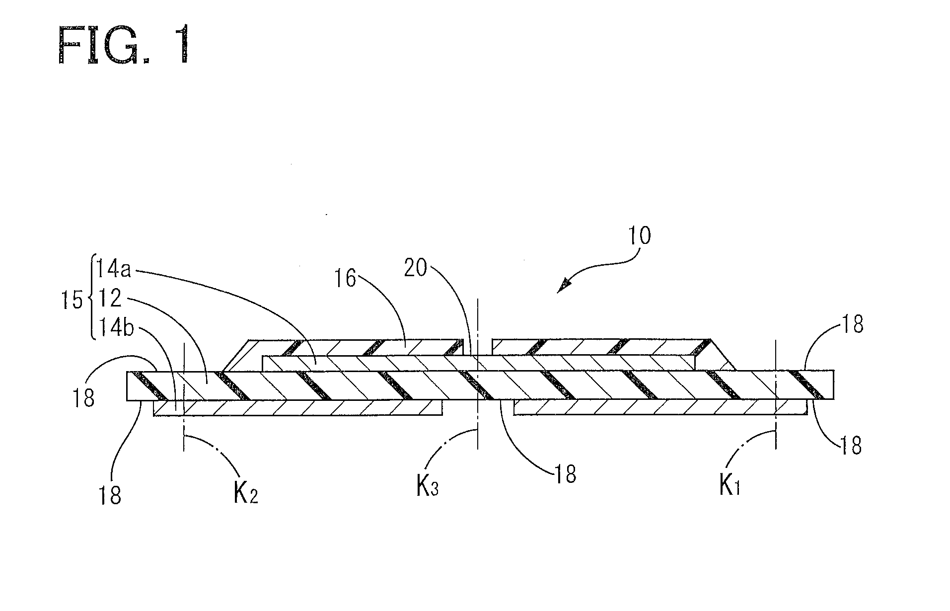
first embodiment
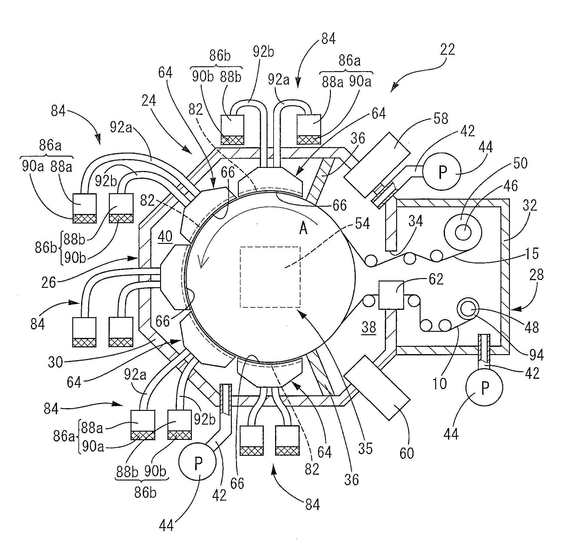
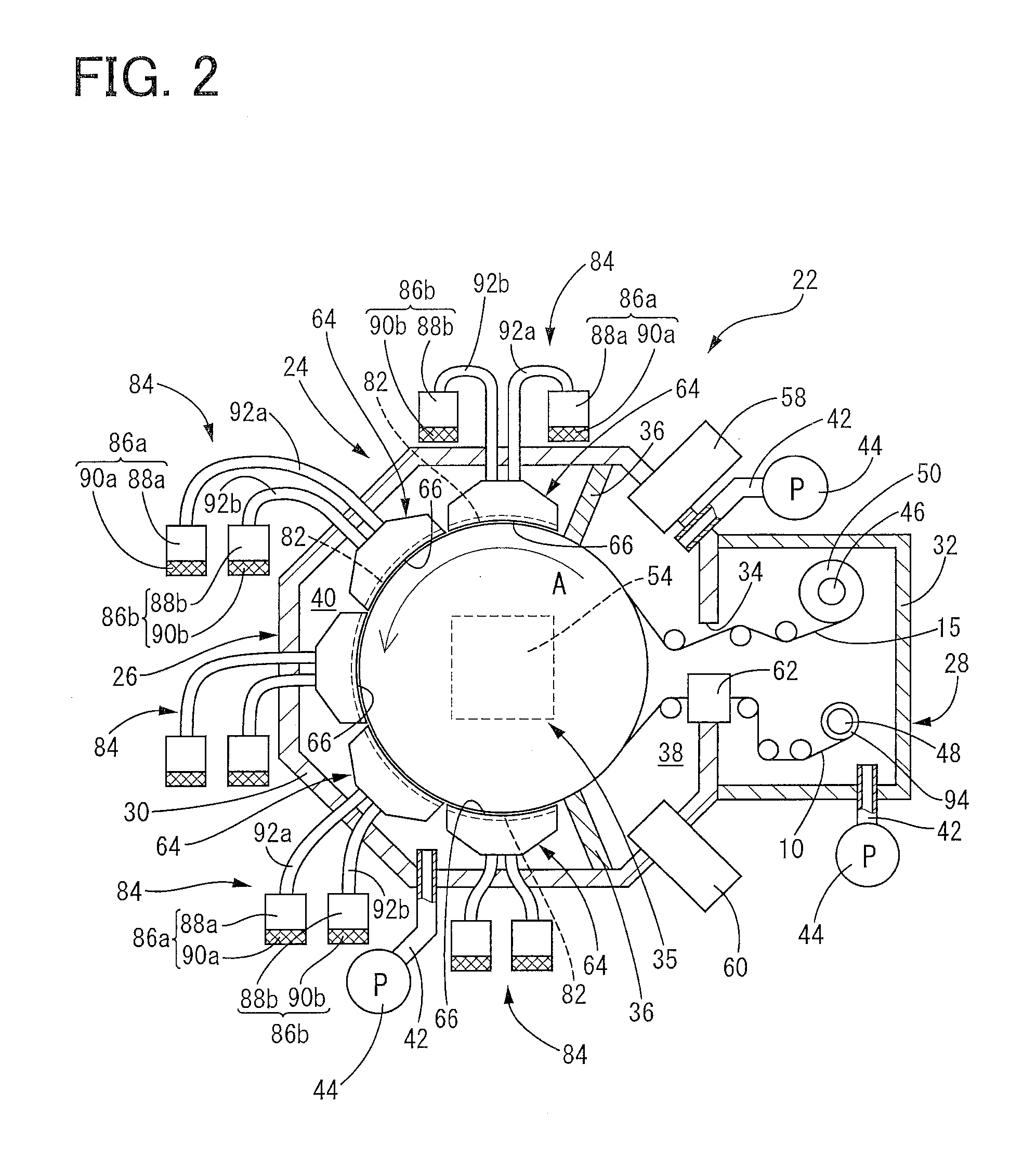
[0048]The above-described laminated body 10 is produced by a production apparatus 22 of the present invention shown in FIG. 2, for example. Hereinafter, the production apparatus 22 of the laminated body in accordance with the present invention will be described in detail.
[0049]As apparent from FIG. 2, the production apparatus 22 in accordance with the present embodiment includes a vacuum chamber 24 having a predetermined size. The vacuum chamber 24 includes a main chamber 26 and an auxiliary chamber 28. The main chamber 26 is surrounded by a first peripheral wall 30. The auxiliary chamber 28 is surrounded by a part of the first peripheral wall 30 and a second peripheral wall 32. The main chamber 26 and the auxiliary chamber 28 are communicated with each other through a window 34 that is formed at the part of the first peripheral wall 30, which surrounds the auxiliary chamber 28 with the second peripheral wall 32.
[0050]At the center in the main chamber 26, a can roller 35 as a rotary...
second embodiment
[0108]Specifically, as apparent from FIG. 5, in the production apparatus 96 in accordance with the second embodiment, the vacuum chamber 24 only has the main chamber 26. The vacuum chamber 24 can be in a vacuum state by the vacuum pump 44 that is connected to the end of one exhaust pipe 42.
[0109]In the vacuum chamber 24, the can roller 35 including the cooling mechanism 54 is rotatably provided. Around the can roller 35, six blowoff members 64a, 64b, 64c, 64d, 64e, 64f are provided so as to be in line in the circumferential direction of the can roller 35. Although not shown in the drawing, the six blowoff members 64a, 64b, 64c, 64d, 64e, 64f have the same structure as the blowoff members 64 provided in the production apparatus 22 of the first embodiment, i.e., the mixing chamber 76 and the deposition chamber 78 are provided in the respective blowoff members 64. However, the shield bar 82 is not provided in the vapor outlet 66 of each of the blowoff members 64b, 64c, 64d.
[0110]At th...
PUM
| Property | Measurement | Unit |
|---|---|---|
| Thickness | aaaaa | aaaaa |
| Thickness | aaaaa | aaaaa |
| Distance | aaaaa | aaaaa |
Abstract
Description
Claims
Application Information