

Composite resinous material particles and process for producing same
a technology of composite materials and resinous materials, which is applied in the direction of non-metal conductors, conductors, metal/alloy conductors, etc., can solve the problems of low conductivity of conductive resin itself, large amount of carbon black to be added, and inability to display sufficient performance in practical use. to achieve the effect of high conductive molding product, low cost and high conductivity of composite material particles
- Summary
- Abstract
- Description
- Claims
- Application Information
AI Technical Summary
Benefits of technology
Problems solved by technology
Method used
Image

Examples
example 1
Production of Composite Resin Material Particles
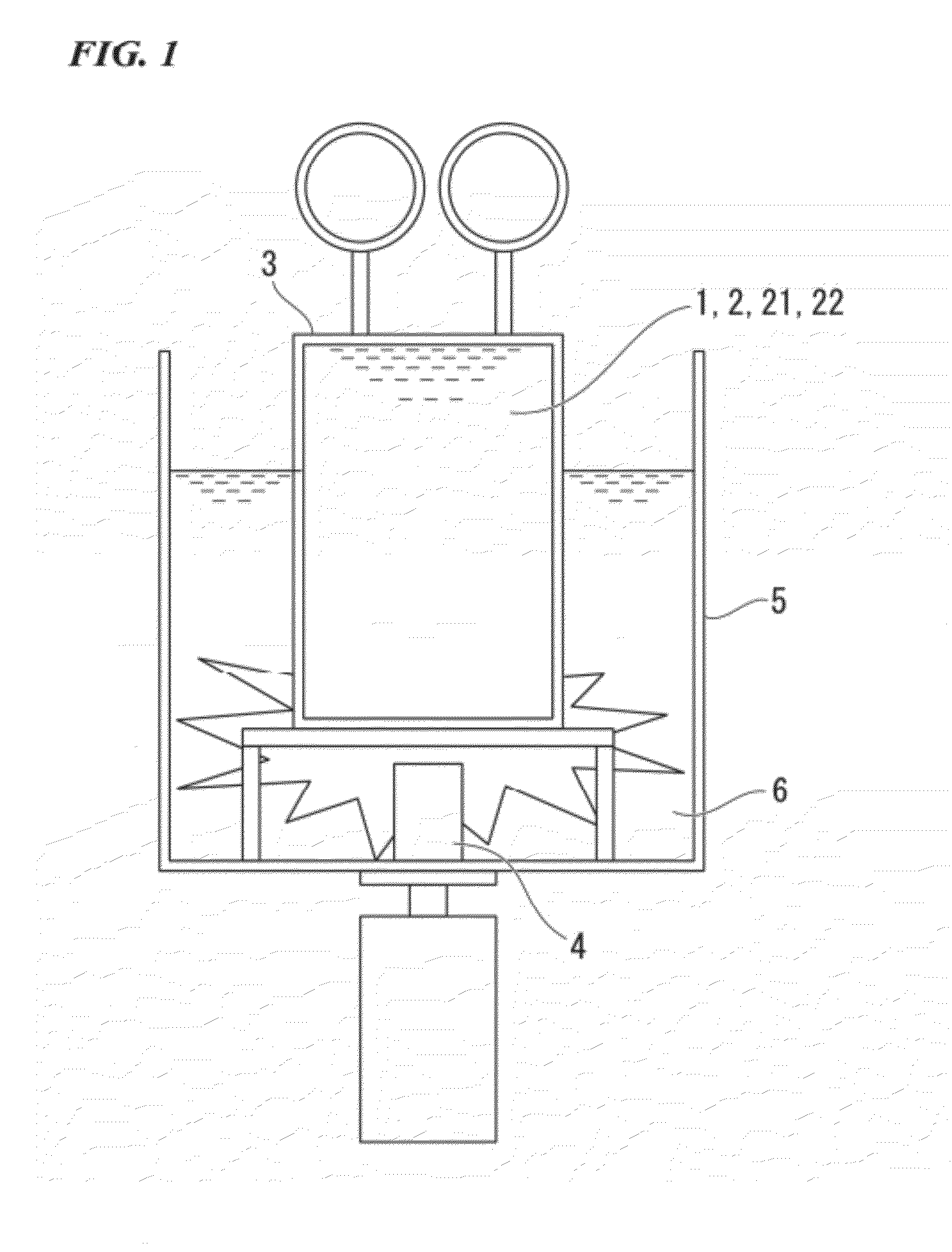
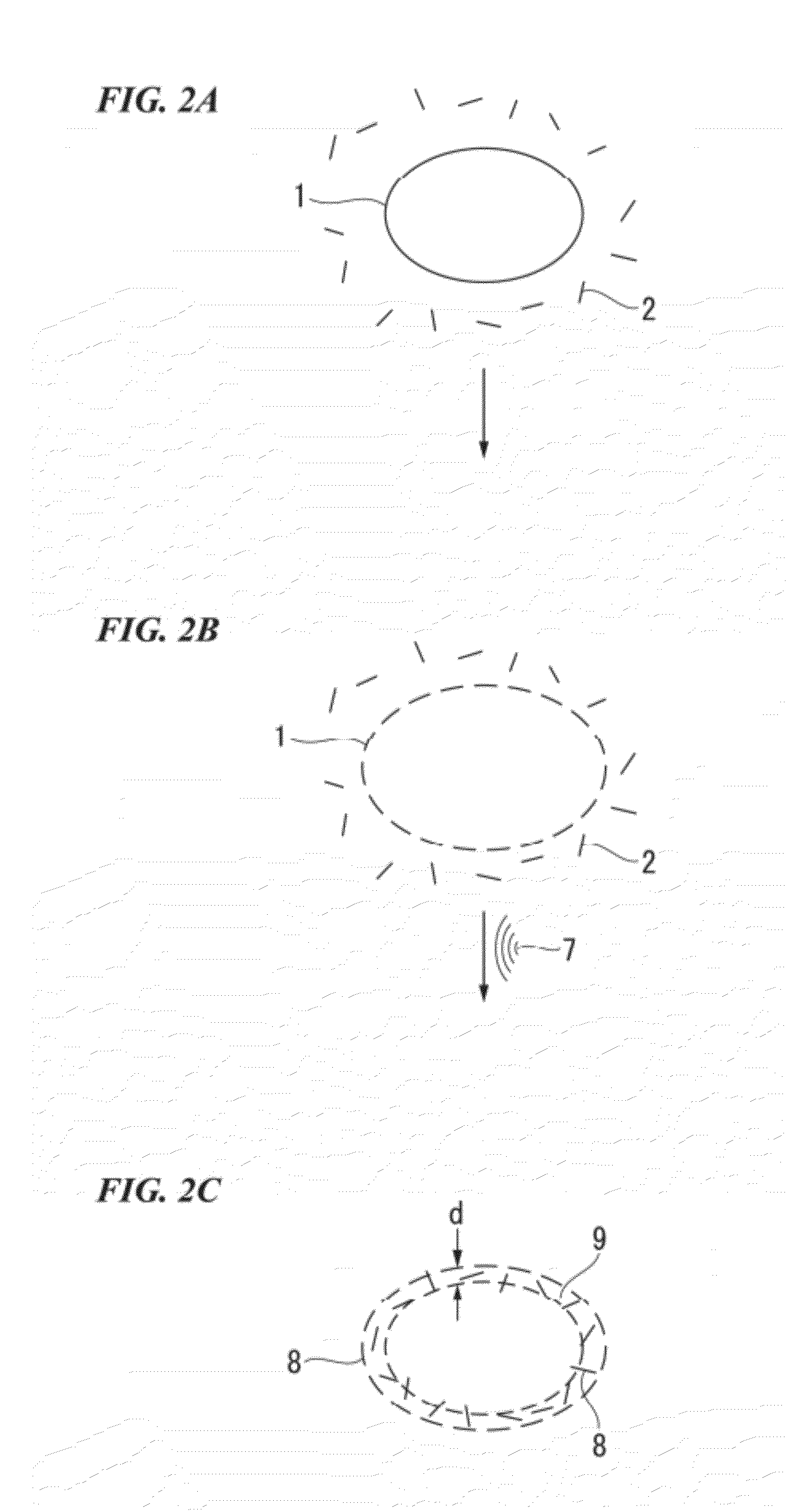
[0105]Into a pressure vessel were filled 170 mg of polycarbonate (PC) pellets having an average grain diameter of 3 mm, 5 g of a dispersion liquid containing carbon nanotubes (CNT) at a concentration of 0.3 wt % in ethanol as a solvent, and 48 g of liquid carbon dioxide. The pressure vessel was then soaked in a water bath filled with hot water kept at 65° C., and was subjected to supercritical dispersion with ultrasonic waves for 10 hours by using an ultrasonic oscillator that had been provided under the water bath (the ultrasonic wave generator is the GSD-600AT manufactured by Ginsen). Two types of CNT, the Baytubes C150P (average diameter of φ11 nm) manufactured by Bayer Holding Ltd. and the VGCF-S (average diameter of φ80 nm) manufactured by Showa Denko K.K., were used.
[0106]After the treatment, the pressure vessel was opened to evaporate the liquid carbon dioxide. Then, the pressure vessel was treated in a normal pressure electric ...
example 2
Production of Molding Product
[0108]Into a pressure vessel were filled 16 g of a polytetrafluoroethylene (PTFE) powder having an average grain diameter of 5 μm, 48 g of a dispersion liquid containing carbon nanotubes (CNT) at a concentration of 1.0 wt % in ethanol as a solvent so that the CNT weight with respect to PFTE would be 3 wt %, and 48 g of liquid carbon dioxide so that the ratio of the liquid carbon dioxide to the solvent would be 1. Two types of CNT, the Baytubes C150P (average diameter of φ11 nm) manufactured by Bayer Holding Ltd. and the VGCF-S (average diameter of φ80 nm) manufactured by Showa Denko K.K., were used.
[0109]This pressure vessel was soaked in a water bath filled with hot water kept at 65° C., and was subjected to supercritical dispersion with ultrasonic waves for 10 hours by using an ultrasonic oscillator that had been provided under the water bath (the ultrasonic wave generator is the GSD-600AT manufactured by Ginsen). After the treatment, the pressure vess...
PUM
| Property | Measurement | Unit |
|---|---|---|
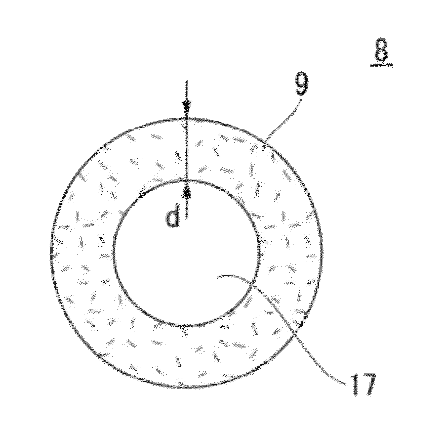
| thickness | aaaaa | aaaaa |
| diameter | aaaaa | aaaaa |
| length | aaaaa | aaaaa |
Abstract
Description
Claims
Application Information