Drive circuit for switching element

a driving circuit and switching element technology, applied in the direction of pulse generator, pulse technique, dynamo-electric converter control, etc., can solve the problems of reducing the reliability of the gate oxide film of the igbt, and increasing the gate voltage of the igb

Active Publication Date: 2012-10-04
DENSO CORP
View PDF4 Cites 24 Cited by
  • Summary
  • Abstract
  • Description
  • Claims
  • Application Information

AI Technical Summary

Benefits of technology

[0009]In the above disclosure, current capable of flowing in the switching element becomes larger, as a potential difference between the open / close control terminal and either one of the pair of ends in the current flow path of the switching element becomes larger. Due to this, if the potential difference is restricted, then the current flowing in the switching element can be restricted. From this, in the above disclosure, the potential difference is restricted to the reference voltage. This can avoid a situation where excessively large current flows in the switching element in association with a switching to the on-state of the switching element.
[0011]In the above disclosure, a condition for a start of the predetermined period is configured by a plurality of conditions. This can increase a resistance to noise of a judgment on whether to meet the condition for the start, compared with a case where the condition is configured by a single condition.
[0018]In the above disclosure, in case of abnormality where current flowing in the switching element is equal to or more than the threshold current, the restriction unit is prohibited from releasing its restriction. This can reliably avoid a situation where current flowing in the switching element becomes further larger.
[0020]In the above disclosure, in case of abnormality where current flowing in the switching element is equal to or more than the threshold current, the switching element is forcibly turned off. This can reliably avoid a situation where current flowing in the switching element becomes further larger.

Problems solved by technology

Excessive increase in the upper limit may cause decrease in reliability of the gate oxide film of the IGBT.
However, when the IGBT to be driven is configured by a series connection of a switching element at a high-voltage side and a switching element at a low-voltage side, if abnormality where feedthrough current flows in the IGBT occurs, a switching to an on-state of the IGBT results in a rapid and excessive increase in current flowing in the IGBT.
This leads to increase in the gate voltage of the IGBT, and therefore, prior to a switching to the constant voltage, such excessively large current as to cause decrease in reliability of the IGBT may flow in the IGBT.

Method used


Image

  • Drive circuit for switching element
  • Drive circuit for switching element
  • Drive circuit for switching element

Examples


first embodiment

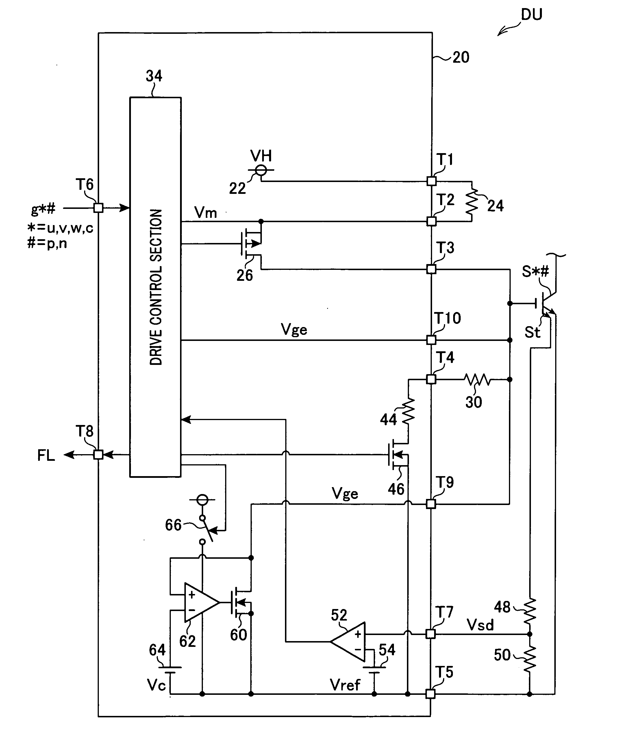
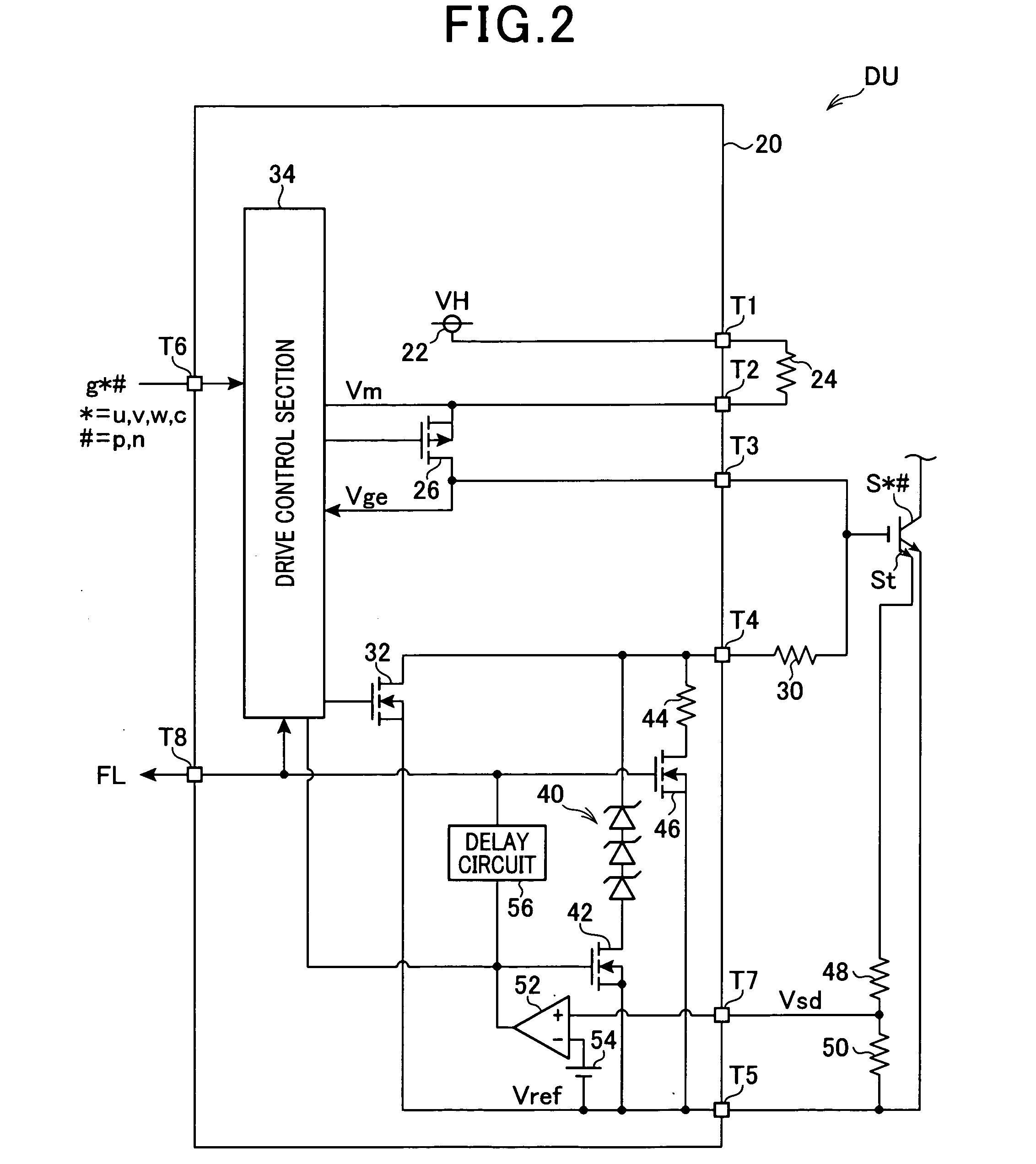
[0035]Hereinafter, referring to FIGS. 1 to 4, a first embodiment is described. In the first embodiment, a drive circuit for a switching element according to the present invention is applied to a power conversion circuit connected to a vehicle's main machine mounted on a vehicle.

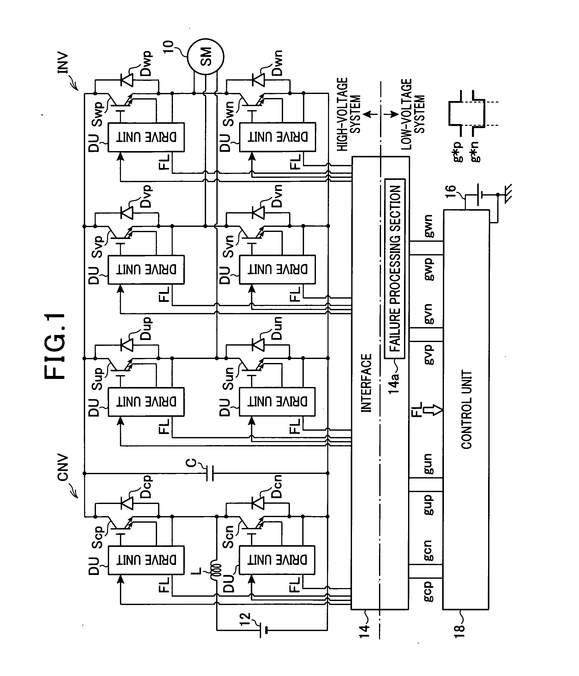
[0036]FIG. 1 is a diagram illustrating a general configuration of a control system (motor system) for a vehicle's main machine, according to the present embodiment. A motor generator 10 is a vehicle's main machine which is mechanically connected to drive wheels of a vehicle, not shown. The motor generator 10 is also connected to a high-voltage battery 12 via an inverter INV and a step-up converter (also called a boost converter) CNV, which compose a power conversion circuit.

[0037]The step-up converter CNV includes a capacitor C, a pair of switching elements Scp and Scn, and a reactor L. The pair of switching elements Scp and Scn are connected parallel to the capacitor C. The reactor L connects the connecting ...

second embodiment

[0070]Referring to FIG. 5, hereinafter is described a second embodiment, focusing on the differences from the first embodiment. In the second and the subsequent embodiments, the components identical with or similar to those in the first embodiment are given the same reference numerals for the sake of omitting unnecessary explanation.

[0071]FIG. 5 shows a procedure of an on-operation process of the switching element S*# according to the present embodiment. This process is repeatedly performed by the drive control section 34 at a predetermined interval.

[0072]In a series of steps in FIG. 5, at step 10a, after the operation signal S*# for the switching element S*# to be driven is switched from the off-operation command to the on-operation command, the drive control section 34 judges whether or not the constant-current control is started, in order to judge whether or not there is a start timing of a period during which the clamp switching element 42 is controlled to be turned on. Here, a ...

third embodiment

[0074]Referring to FIG. 6, hereinafter is described a third embodiment, focusing on the differences from the first embodiment.

[0075]FIG. 6 shows a procedure of an on-operation process of the switching element S*# according to the present embodiment. This process is repeatedly performed by the drive control section 34 at a predetermined interval.

[0076]In a series of steps in FIG. 6, at step 10b, the drive control section 34 judges whether or not a logical conjunction of two conditions (x1) and (x2) is true, where (x1) is that the operation signal S*# for the switching element S*# to be driven is switched from the off-operation command to the on-operation command, and (x2) is that the gate voltage Vge is equal to or less than a predetermined voltage V2 (V242 is controlled to be turned on. Here, the purpose of the condition (x2) that the gate voltage Vge is equal to or less than a predetermined voltage V2 (V234 from falsely recognizing that the operation signal S*# is the on-operation ...


PUM


Abstract

A drive circuit for a switching element includes a constant-current control unit and a restriction unit. The constant-current control unit performs a constant-current control for charging an open / close control terminal of a switching element to be driven which is a voltage-controlled switching element with electric charge for turning on the switching element. The restriction unit restricts, to a reference voltage, a voltage between the open / close control terminal and a first end of a pair of ends of a current flow path of the switching element for a predetermined period following a start of the constant-current control within a charging process period during which the open / close control terminal is charged with the electric charge such that the switching element is turned on.

Description

CROSS-REFERENCE TO RELATED APPLICATION[0001]This application is based on and claims the benefit of priorities from earlier Japanese Patent Application No. 2011-069485 filed Mar. 28, 2011 and No. 2012-020636 filed Feb. 2, 2012, the descriptions of which are incorporated herein by reference.BACKGROUND OF THE INVENTION[0002]1. Technical field of the Invention[0003]The present invention relates to a drive circuit for a switching element, and in particular, to a drive circuit for a switching element including a constant-current control unit that performs a constant-current control for charging an open / close control terminal of a switching element to be driven which is a voltage-controlled switching element with electric charge for turning on the switching element.[0004]2. Related Art[0005]As a drive circuit for a switching element, there is proposed a circuit that uses a constant-current circuit to charge a gate of an insulated gate bipolar transistor (IGBT) to be driven, as disclosed by...

Claims


Application Information

Patent Timeline
Patent Type & Authority Applications(United States)
IPC IPC(8): H02P27/06H03K17/06
CPCH03K17/08128H03K17/0828H02M7/5387H02M1/32
Inventor KOMATSU, TAKEYASUHAMANAKA, YOSHIYUKIMAEBARA, TSUNEOMIURA, RYOTARO
Owner DENSO CORP
Why Eureka
Try Eureka