Luminescence measuring apparatus and microbe counting apparatus

a technology of microbe counting and measuring apparatus, which is applied in the direction of material analysis, optical radiation measurement, instruments, etc., can solve the problems of inability to detect microbes in terms of cleanness evaluation, so as to improve the reliability of a photodetector, improve the sensitivity, and increase the sensitivity

Inactive Publication Date: 2012-10-04
HITACHI LTD
View PDF5 Cites 16 Cited by
  • Summary
  • Abstract
  • Description
  • Claims
  • Application Information

AI Technical Summary

Benefits of technology

[0023]In the ATP method, an ATP amount of 1 amol can be measured through the increase in sensitivity. Therefore, if several microbes are present, in principle, the microbes can be detected. However, in microbe measurement in cleanness management in a pharmaceutical manufacturing facility and a regenerative medicine facility, apparatus performance for guaranteeing without limit that viable cell counts is zero or one is essential. Therefore, in addition to the improvement of sensitivity, it is an object to improve reliability of a photodetector that does not output a misdetection result. This is because, if it is determined by misdetection that “contamination” occurs, disposal of manufactured products and stop of a manufacturing line are requested, leading to a fall in productivity. The misdetection indicates lights in a visible light region deriving from an external factor other than a collected sample (extraneous lights) rather than bioluminescence due to ATP derived from viable cells contained in a sample collected for contamination evaluation. The extraneous lights are roughly divided into four.

Problems solved by technology

This is because, if it is determined by misdetection that “contamination” occurs, disposal of manufactured products and stop of a manufacturing line are requested, leading to a fall in productivity.
First extraneous light is caused by a light blocking failure of an apparatus ideally configured to meet darkroom specifications.
Therefore, misdetection occurs in terms of cleanness evaluation.

Method used


Image

  • Luminescence measuring apparatus and microbe counting apparatus
  • Luminescence measuring apparatus and microbe counting apparatus
  • Luminescence measuring apparatus and microbe counting apparatus

Examples


example 1

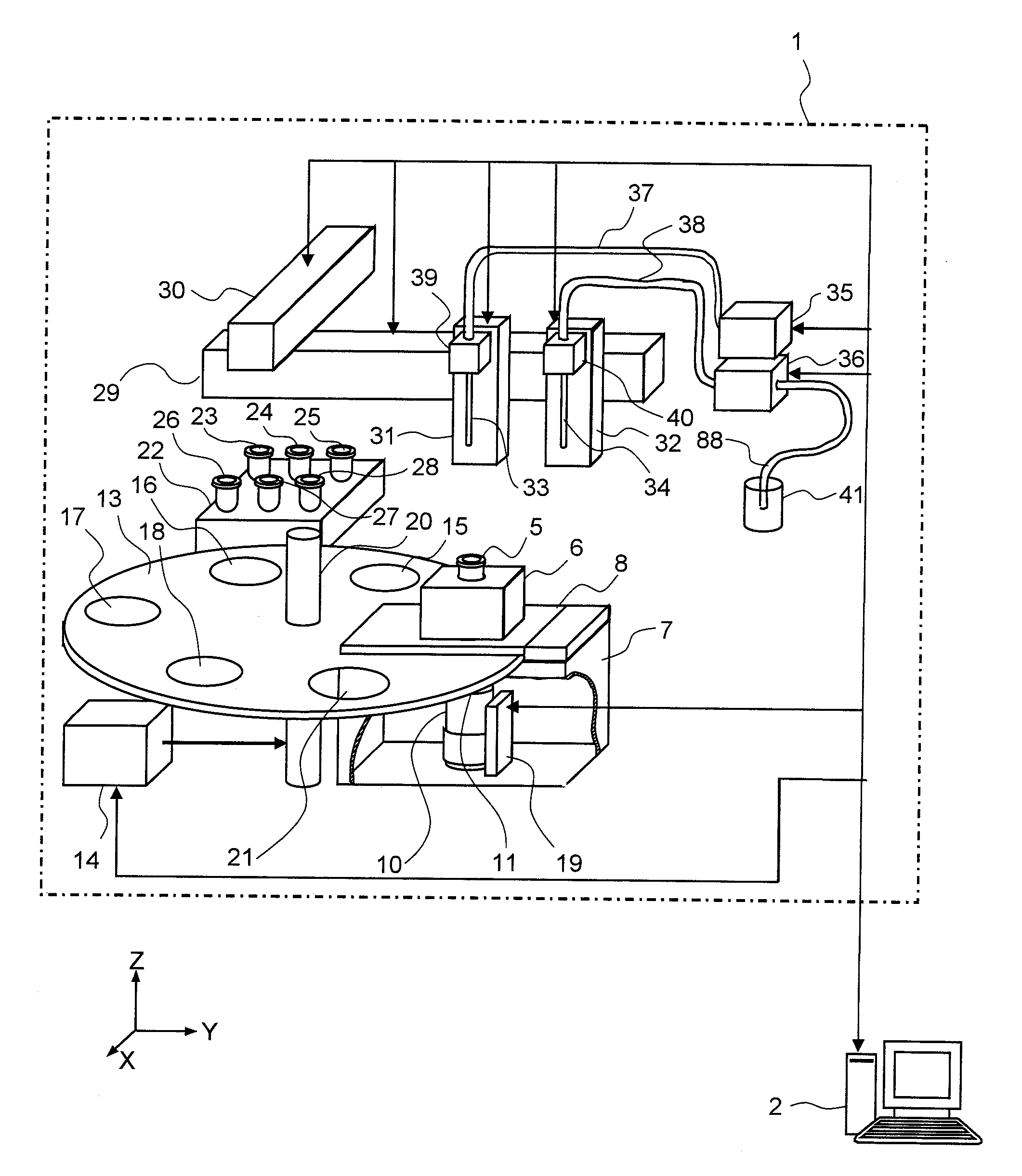
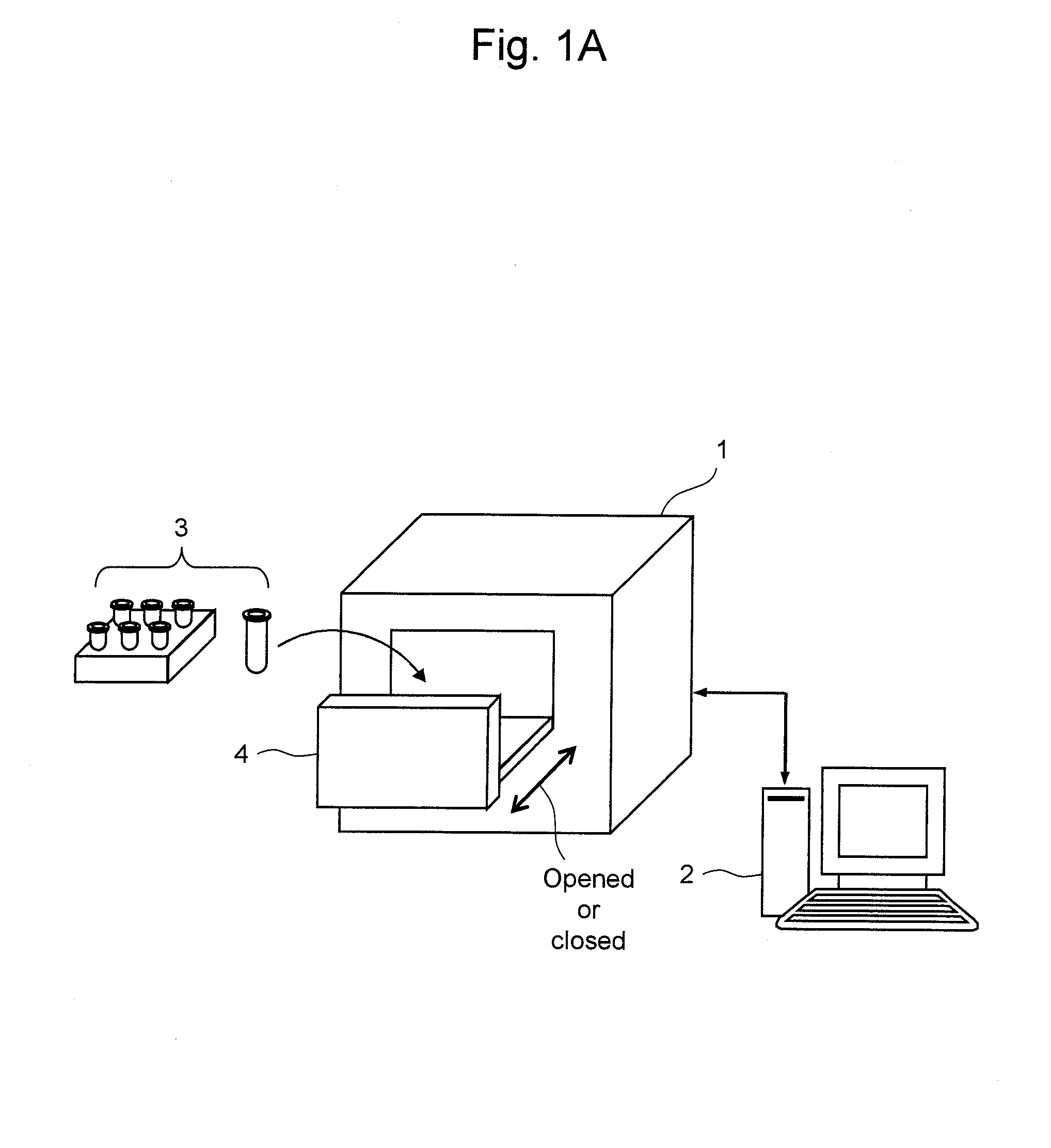
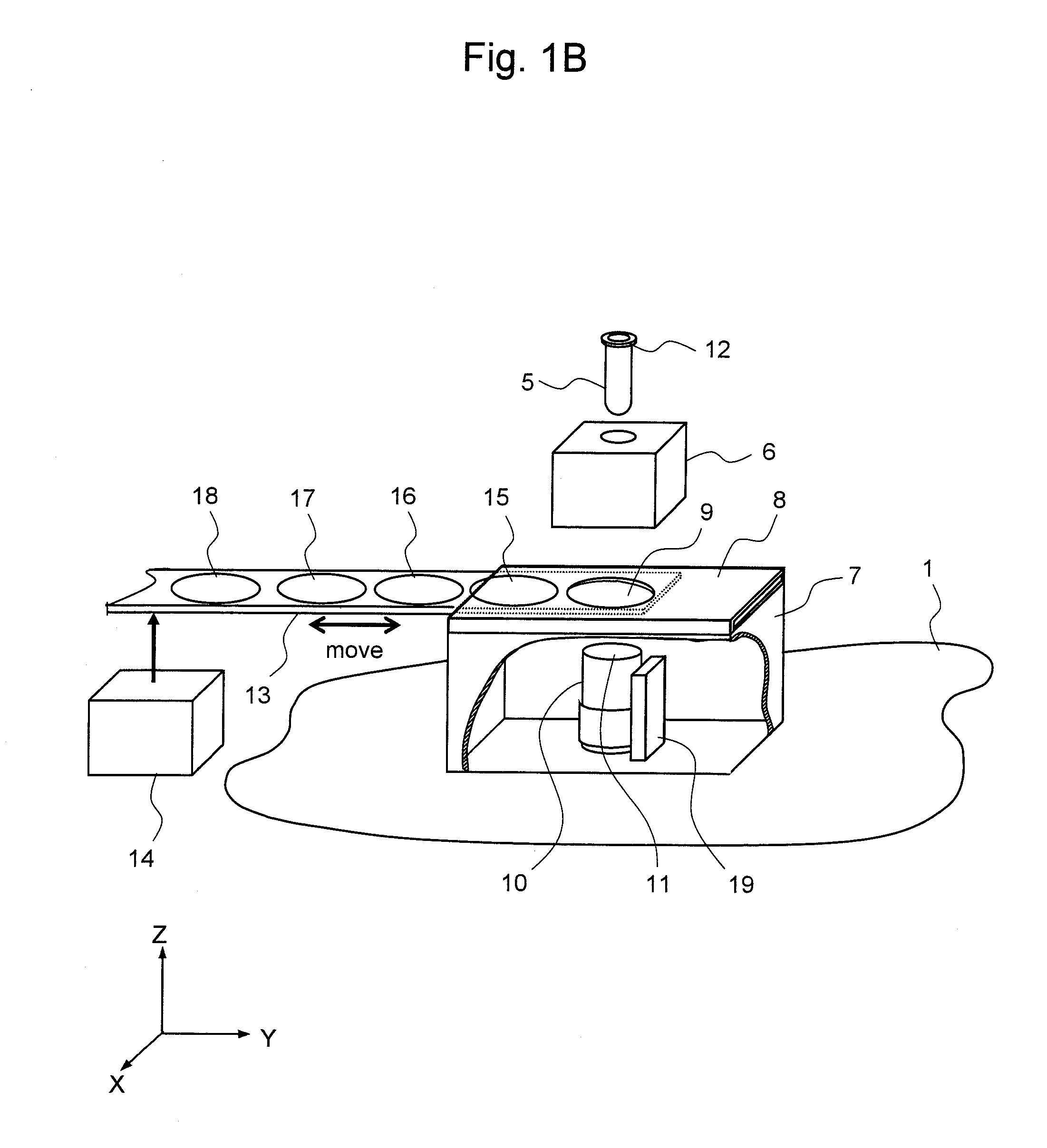
[0113]FIGS. 1A, 1B, and 1C show a schematic configuration of a luminescence measuring apparatus according to a first embodiment. FIG. 1A is a general example of a schematic diagram of the luminescence measuring apparatus and is an external view of an apparatus containing a luminescence measuring apparatus 1 and a control apparatus 2 for controlling the luminescence measuring apparatus 1. The luminescence measuring apparatus 1 has an opening and closing stage 4 that are opened and closed when at least one consumable kit 3 for measurement such as a sample container or a reagent container is set. In a state where the opening and closing stage 4 is closed, the inside of the luminescence measuring apparatus 1 is a dark room which is completely light-blocking and interferes with entering of extraneous light. As the consumable kit 3 for measurement, two sets of a reagent / sample container holder 22 and a measurement container 5 are shown. However, when a supply form of a reagent, for exampl...

example 2

[0123]FIGS. 2A and 2B show a schematic configuration of a luminescence measuring apparatus according to a second embodiment. The luminescence measuring apparatus according to this embodiment comprises a solution dispenser in addition to the components in the first embodiment.

[0124]In FIG. 2A, a solution dispenser system and a reagent / sample container holder 22, in which a reagent and a measurement sample are set, are added to the apparatus configuration in the first embodiment in which the tabular optical filter setting holder 13 in the slide table form shown in FIG. 1B is used. In FIG. 2B, the solution dispenser system and the reagent / sample container holder 22, in which a reagent and a measurement sample are set, are added to the apparatus configuration in the first embodiment in which the tabular optical filter setting holder 13 in the turntable form shown in FIG. 1C is used. The consumable kit 3 for measurement shown in FIG. 1A is equivalent to the reagent / sample container holde...

example 3

[0139]In this example, an operation flow is explained in which spectrometry via an optical filter is added when viable cell count is performed using the ATP method.

[0140]FIGS. 7A and 7B are flowcharts for explaining a procedure of luminescence measurement and viable cell count (a typical example). First, the opening and closing stage 4 is opened (S701). The first to sixth solution containers (23, 24, 25, 26, 27, and 28), in which a collected microbial sample to be measured, an ATP eliminating solution, an ATP extraction solution, and other plural nozzle washing solutions are stocked, are set in the reagent / sample container holder 22. The measurement container 5, in which a luciferin-luciferase luminescent reagent is stocked, is set in a predetermined position of the luminescence measuring apparatus 1, i.e., in the measurement container holder 6 (S702). It is assumed that the ATP eliminating solution is stocked in the first solution container 23, the ATP extraction solution is stocke...


PUM


Abstract

The present invention relates to a luminescence measuring apparatus for detecting, at high sensitivity and high accuracy, chemoluminescence and bioluminescence of a substance contained in a sample. Specifically, the present invention provides an apparatus for measuring an amount of luminescence in a sample, comprising: a container for the sample; a photodetector for detecting luminescence from the container; and at least one optical filter inserted between the photodetector and the container, and/or a pH modifier added to the container, wherein the photodetector performs measurement of light emitted from the container at all wavelength regions and spectrometry at a specific wavelength range, and/or measurement of light, the intensity of which is changed by the pH modifier. The present invention also relates to a microbe counting apparatus based on luminescence detection of ATP in a viable microbial cell.

Description

CLAIM OF PRIORITY[0001]The present application claims priority from Japanese patent application JP 2011-076637 filed on Mar. 30, 2011, the content of which is hereby incorporated by reference into this application.BACKGROUND OF THE INVENTION[0002]1. Field of the Invention[0003]The present invention relates to a luminescence measuring apparatus for detecting, at high sensitivity and high accuracy, chemoluminescence and bioluminescence of a substance contained in a sample. The present invention also relates to a microbe counting apparatus based on luminescence detection of ATP in a viable microbial cell.[0004]2. Background Art[0005]With the development of genetic engineering, tissue engineering, and basic medical science, cell therapy and regenerative medicine enabling regeneration and reconstruction of organs that make use of biological tissue and cultured cells are being developed. With the development of cell therapy and regenerative medicine, research and development of biopharmac...

Claims


Application Information

Patent Timeline
Patent Type & Authority Applications(United States)
IPC IPC(8): G01B9/02G01J1/00
CPCG01N21/76G01N21/6486G02B21/16
Inventor NODA, HIDEYUKIOKANOJO, MASAHIRO
Owner HITACHI LTD
Why Eureka
Try Eureka