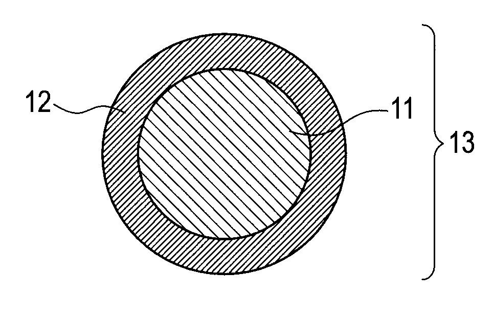
Conductive member

a technology of conductive parts and components, applied in the field of conductive parts, can solve the problems of insufficient inventions to solve problems, and achieve the effect of improving the performance of the conductive parts

Inactive Publication Date: 2012-10-04
CANON KK
View PDF4 Cites 34 Cited by
  • Summary
  • Abstract
  • Description
  • Claims
  • Application Information

AI Technical Summary

Benefits of technology

[0013]According to the present invention, there is provided such a conductive member that a change in its electrical resistance value caused by its long-term use is reduced to the extent possible.

Problems solved by technology

As a result of investigations on the inventions according to Patent Literature 1 and Patent Literature 2 conducted by the inventors of the present invention, however, the inventors have acknowledged that the movement and uneven distribution of a quaternary ammonium ion and an anion in the conductive layer are inevitable even now, and hence the inventions are still insufficient to solve the problems.

Method used


Image

  • Conductive member
  • Conductive member
  • Conductive member

Examples


example 1

[0056]100 Grams of an epichlorohydrin-ethylene oxide-allyl glycidyl ether (EP / EO / AGE) terpolymer (trade name: EPION 301, manufactured by DAISO CO., LTD.) were dissolved in 1,000 ml of N,N-dimethylformamide (DMF). To the solution were added 8 g of a 40-mass % aqueous solution of methylamine (containing 3.2 g of methylamine) and then the mixture was refluxed by heating under a nitrogen atmosphere at a temperature of 50° C. for 12 hours. Next, the reaction liquid was concentrated and exsiccated. Thus, such an EP / EO / AGE terpolymer that a quaternary ammonium ion was introduced into an epichlorohydrin unit portion was obtained. The terpolymer is defined as a modified epichlorohydrin rubber No. 1.

[0057]Next, materials shown in Table 1 were added to 100 parts by mass of the modified epichlorohydrin rubber No. 1 and then the contents were mixed with an open roll. Thus, an unvulcanized rubber composition No. 1 was obtained.

TABLE 1MaterialPart(s) by massModified epichlorohydrin rubber No. 1100...

example 2 to example 12

[0070]Modified epichlorohydrin rubbers No. 2 to No. 12 were synthesized in the same manner as in the modified epichlorohydrin rubber No. 1 according to Example 1 except that the epichlorohydrin rubber as a raw material, the kind of amine used in the modification, and the addition amount of the amine were changed as shown in Table 4. It should be noted that an alphabetical letter for the kind of epichlorohydrin rubber as a raw material in Table 4 represents a material shown in Table 5. Next, unvulcanized rubber compositions No. 2 to No. 12 were prepared in the same manner as in Example 1 except that the resultant modified epichlorohydrin rubbers No. 2 to No. 12 were used, and then charging rollers No. 2 to No. 12 were produced with the compositions. Those charging rollers were subjected to Evaluations 1 to 3 of Example 1.

TABLE 4ModifiedEpichloro-Amineepichloro-hydrinActualhydrinrubber asadditionExamplerubber No.raw materialKindamount (g)11JMethylamine3.222Dimethylamine4.733Trimethyla...

example 13

[0071]100 Grams of the epichlorohydrin rubber J as a raw material and 8.1 g of triethylamine were mixed with an open roll. Thus, a modified epichlorohydrin rubber No. 13 was obtained. An unvulcanized rubber composition No. 13 was prepared in the same manner as in Example 1 except that the resultant modified epichlorohydrin rubber No. 13 was used, and then a charging roller No. 13 was produced with the compositions. This charging roller was subjected to Evaluations 1 to 3 of Example 1.


PUM

PropertyMeasurementUnit
thicknessaaaaaaaaaa
glass transition temperatureaaaaaaaaaa
boiling pointaaaaaaaaaa

Abstract

Provided is such a conductive member that a change in its electrical resistance value caused by its long-term use is reduced to the extent possible. The conductive member has a conductive support and a conductive layer, the conductive layer contains a rubber composition formed of a modified epichlorohydrin rubber, and the modified epichlorohydrin rubber has a unit represented by the following formula (1). In the formula (1), R1, R2, and R3 each independently represent hydrogen or a saturated hydrocarbon group having 1 to 18 carbon atoms.

Description

CROSS-REFERENCE TO RELATED APPLICATIONS[0001]This application is a continuation of International Application No. PCT / JP2012 / 001915, filed Mar. 21, 2012, which claims the benefit of Japanese Patent Application No. 2011-072404, filed Mar. 29, 2011.BACKGROUND OF THE INVENTION[0002]1. Field of the Invention[0003]The present invention relates to a conductive member to be used in an electrophotographic image-forming apparatus.[0004]2. Description of the Related Art[0005]Additional lengthening of the lifetime of an electrophotographic apparatus has been required in recent years. Accordingly, slight changes in its physical properties that have not been perceived as problems so far may cause image defects owing to its long-term use. In particular, a change in its electrical resistance value serves as an important factor for high durability of a conductive member.[0006]A conductive member including a conductive layer obtained by adding an ionic conductive agent to a polar polymer such as a hy...

Claims


Application Information

Patent Timeline
Patent Type & Authority Applications(United States)
IPC IPC(8): G03G21/18B32B25/00G03G15/00
CPCB32B15/06B32B15/18B32B25/02B32B25/14B32B1/08B32B2457/00G03G15/0818G03G15/1685B32B2264/104B32B2264/108B32B2307/202G03G15/0233Y10T428/31855B05D3/007Y10T428/31522
Inventor MURANAKA, NORIFUMIYAMADA, SATORUYAMAUCHI, KAZUHIROTSURU, SEIJIMURANAKA, YUKA
Owner CANON KK
Why Eureka
Try Eureka