Production method of connection structure

Active Publication Date: 2012-10-11
DEXERIALS CORP
View PDF8 Cites 15 Cited by
  • Summary
  • Abstract
  • Description
  • Claims
  • Application Information

AI Technical Summary

Benefits of technology

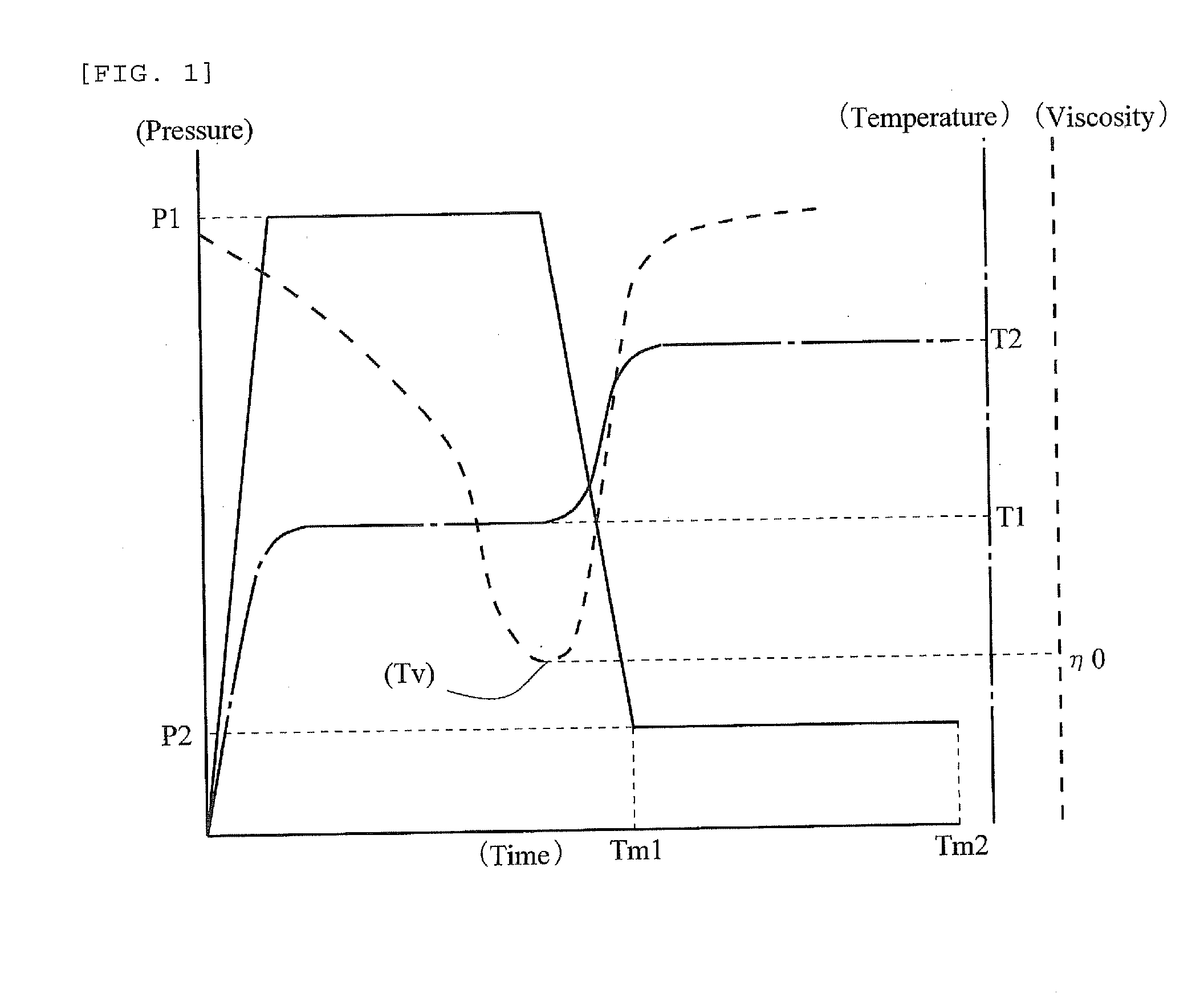
[0015]The production method of the present invention uses low temperature melting solder particles as conductive particles constituting an anisotropic conductive adhesive, and low temperature curable acrylic-based thermosetting resin, instead of an epoxy-based thermosetting adhesive, as an insulating thermosetting adhesive constituting an anisotropic conductive adhesive. Moreover, a specific magnitude relationship is set among a melting temperature of the solder particles, a temperature at which the anisotropic conductive adhesive shows a minimum melt viscosity, a preheating temperature, and a

Problems solved by technology

However, in the case of Patent Literature 1, there has been a problem that a high temperat

Method used


Image

  • Production method of connection structure

Examples


Example

Examples 1 and 2, and Comparative Examples 1 to 5

[0047]First, anisotropic conductive adhesives A and B were prepared as described below.

(Anisotropic Conductive Film A)

[0048]30 parts by mass of a bis-A type phenoxy resin (YP50 manufactured by Nippon Steel Chemical Co., Ltd.), 30 parts by mass of a liquid acrylic compound (EB3701 manufactured by DAICEL-CYTEC Company LTD.), an organic peroxide curing agent (Perocta O manufactured by NOF CORPORATION), 1 part by mass of an acrylic-based silane coupling agent (A-172 manufactured by Momentive Performance Materials Inc.) were mixed. Furthermore, an eutectic SnBi solder having an average particle size of 10 μm and a melting temperature of 138° C. was added so that an amount of the solder becomes 20% by mass in a resin solid component. Then, toluene was added to prepare an anisotropic conductive composition having a solid amount of 50 wt %. The prepared anisotropic conductive composition was coated on a release treated PET by using a bar coat...

Example

[0053]On the other hand, in the case of Comparative Example 1, the heating and pressurizing step was not performed in two stages with a heating temperature of 190° C. and a constant pressure at a low level (0.5 MPa), thereby causing insufficient press. Accordingly, although a short did not occur between the neighboring terminals, a problem was found in the results of a reliability test. In the case of Comparative Example 2, the heating and pressurizing step was not performed in two stages with a constant pressure at a high level (3.0 MPa) and a heating temperature of 190° C. Therefore, a short attributable to a fusion bonding of the solder particles occurred between the neighboring terminals. In the case of Comparative Example 3, in which an anisotropic conductive film B was used, the heating temperature was lower than the melting temperature of the solder particles. Therefore, formation of a metallic bond by the solder particles was not observed. In the case of Comparative Example ...


PUM

PropertyMeasurementUnit
Temperatureaaaaaaaaaa

Abstract

In order to lower the substantial heating temperature of a thermosetting adhesive and to realize favorable connection reliability during connecting an electrical element to a circuit board by anisotropic conductive connection with using solder particles, a product in which solder particles having a melting temperature Ts are dispersed in an insulating acrylic-based thermosetting resin having a minimum melt viscosity temperature Tv is used as an anisotropic conductive adhesive in producing a connection structure by connecting the circuit board and the electrical element to each other by anisotropic conductive connection.

Description

TECHNICAL FIELD[0001]The present invention relates to a method for producing a connection structure in which an electrode of a circuit board and an electrode of an electrical element are connected to each other by anisotropic conductive connection.BACKGROUND ART[0002]It has been proposed that, when a bump of an electrical element such as a semiconductor chip is connected to an electrode of a circuit board by anisotropic conductive connection, an anisotropic conductive film, in which solder particles having a melting temperature of 180 to 185° C. are dispersed in an epoxy-based thermosetting adhesive having a curing temperature of 195 to 200° C., is disposed between the bump of the semiconductor chip and the electrode of the circuit board, and then the obtained product is heated and pressurized so that the solder particles are melted, thereby metallically bonding the bump of the semiconductor chip and the electrode of the circuit board (Patent Literature 1). In this case, preheating ...

Claims


Application Information

Patent Timeline
IPC IPC(8): H05K13/04H05K1/09
CPCH01L24/29H01L24/83H01L2224/2919H01L2224/293H01L2224/83855H01L2924/01004H01L2924/01013H01L2924/01029H01L2924/0103H01L2924/01047H01L2924/01049H01L2924/0105H01L2924/01079H01L2924/01082H01L2924/0781H01L2924/09701H01R4/04H01R43/0242H05K3/323H05K2203/0425H01L2924/01005H01L2924/01006H01L2924/01023H01L2924/01033H01L2924/01045H01L2924/01322H01L2924/014H01L2924/0665H01L2224/29101H01L2924/0132H01L2924/0133C08F2230/085C09J163/10H01L2224/29109H01L2224/29111H01L2224/2929H01L2224/29311H01L2224/29313C09J163/00C09J171/00C08G2650/56H01L2924/07811Y10T29/49149Y10T428/24826H01L2924/00H01L2924/01083H01L2924/01048H01L2924/00012H01L2224/29309H01L2924/00014H01L2924/15787H01L2924/15788C08F230/085C09J133/00C09J5/06
Inventor IGARASHI, SATOSHI
Owner DEXERIALS CORP
Why Eureka
Try Eureka