
Device having reduced friction properties

Inactive Publication Date: 2012-10-18
SCHOTT AG
View PDF14 Cites 20 Cited by
  • Summary
  • Abstract
  • Description
  • Claims
  • Application Information

AI Technical Summary

Benefits of technology

[0014]If a surface is provided with a coating according to the present invention, then it is, for example, possible to move an input device on this surface without “scratching” or undesirable “sticking”, as is typically the case, for example, with a pen having a synthetic tip or a finger on normal glass surfaces. Moreover, the adherence of dirt or fingerprints on the surface is substantially reduced, so that dry cleaning of these contaminants on a surface with reduced adhesion is possible. This is especially advantageous with touch-panel applications.
[0015]In addition, the adherence, or respectively sticking of organic substances, for example oils, such as skin oil, is substantially reduced or respectively practically completely prevented on a substrate provided with the inventive coating, so that fingerprints are largely avoided or respectively are far less visible. Since the skin oil adheres less or practically not at all on the coating, cleaning of the substrate with an inventive coating is also easier. In one embodiment of the present invention the contaminations from organic substances or respectively skin oil can even be wiped off dry. This means that, for example on displays or touch screen panels, the obligatory cleaning agents for organic contaminants can be relinquished.
[0021]In order to provide not only extreme smoothness of the surface, but also a surface which can be easily cleaned with liquid cleaning agents, the inventive layers have contact angles >approximately 50 degrees, for example >70 degrees. Layers having contact angles >50 degrees, for example >70 degrees allow, in addition to the previously described dry cleaning, simple cleaning of the glass surface from contaminants using liquid cleaning agents such as glass cleaners or water. The reduced adherence mechanism which, for example is distinguished by a low coefficient of friction, is substantially responsible for the good cleanability, in particular dry cleaning of the inventive layers or respectively coatings. The inventive layer or respectively coating however, also has a high contact angle which can even reach more than 100°; however decisive for the dry-cleanability is the low adherence of contaminants, such as organic contaminants on the surface of the coating, and not the high angle of contact.
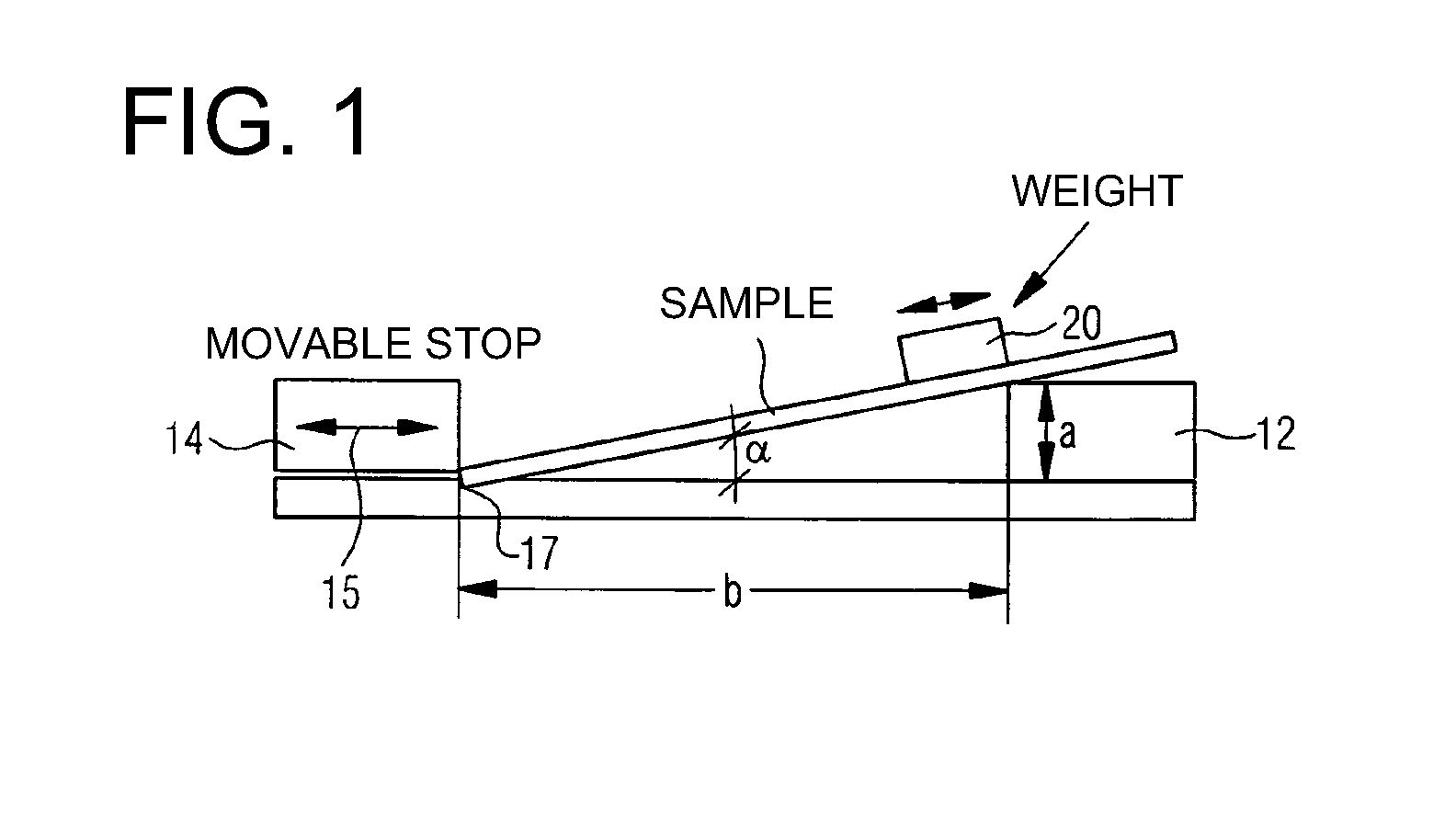
[0039]If an anti-reflective coating is applied, and the anti-reflective coating is provided with a cover layer which has a static coefficient of friction (tan α) in the range between approximately 0.01 and 0.12, for example between 0.02 and 0.1, or between 0.03 and 0.09, then the anti-reflective coating is optically adapted to the cover layer, for example through addition of precursor materials or polymers, so that an anti-reflective effect is provided. The anti-reflective effect is such that, with one- or two-sided application the reflectivity of the entire system is between approximately 0.1% and 7%, for example between 0.1% and 6%, between 0.1% and 5.5%, between 0.1% and 4%, between 0.1% and 2%, or between 0.1% and 1.5% in the visible wavelength range at standard light D65.
[0054]The previously described application method normally delivers cover layers which are only a few nm thick, generally less than approximately 10 nm thick and, for example, represent only a monomolecular saturation of the surface of the coating or respectively the substrate. If cover layers are applied onto anti-reflective coatings or respectively anti-reflection coatings, the thickness of the coating or the refractive index of the entire system consisting of coating and cover layer changes. In order to continue to receive good anti-reflection, the entire system consisting of anti-reflective coating and cover layer may be adapted. Since the cover layer is very thin, the optical system with an anti-reflection coating only needs to be adjusted slightly with such thin cover layers, in order to achieve the desired tint of the residual reflection of the anti-reflection coating, for example by altering the layer structure. It is known to the expert how admixtures can be added to the process described above which effect for example a layer thickness of higher than approximately 10 nm for the anti-reflection coating. An example which can be mentioned is, that simultaneously with the evaporation of the layer having low static friction, an additional polymer compound which leaves behind a transparent layer may be evaporated. The material to reduce the static friction is then incorporated into this layer and can achieve clear optic effect as a layer of more than approximately 10 nm.

Problems solved by technology

Coated substrates, according to those described above often have the problem that the surfaces of these coatings are often very rough in spite of high contact angles.
This results in that glass panels, which for example find use in the field of displays, are scratched by ball pens or pens which leads to an unsteady character image and in addition affects the surface.
However, due to the previously cited problems according to the current state of the art the top glass surface was not able to recognize writing with certainty.
Moreover, the glass surfaces according to the current state of the art were susceptible to contamination for example through finger prints.

Method used


Image

  • Device having reduced friction properties
  • Device having reduced friction properties
  • Device having reduced friction properties

Examples


example 1

Sample 1

[0063]In the trial according to sample 1 the anti-reflection coating was produced according to the sol-gel method. The coating includes three individual layers respectively and possesses the following structure: Substrate+M+T+S.

[0064]The individual layer identified with T contains titanium dioxide (TiO2). The individual layer identified with S contains silicon dioxide (SiO2) and the individual layer identified with M is always drawn from S and T mixed solutions. The float glass substrate is carefully cleaned prior to coating. The dipping solutions are respectively applied in rooms which are air-conditioned to approximately 28° C. at a humidity of 5 to 10 grams per kilogram (g / kg), whereby the draw speeds for each individual layer M / T / S are approximately 275 / 330 / 228 millimeters per minute (mm / min). Drawing of each gel layer is followed by a curing process in air. The curing temperature and the curing time are approximately 180° C. / 20 min after production of the first gel laye...

example 2

Sample 2

[0067]The example-sample 2 is a one-sided anti-reflection coating which is applied as follows in the sputtering process: The coating is deposited in an inline unit in a mid-frequency (MF) sputtering process through magnetron sputtering, whereby the substrate is positioned on a so-called carrier and is transported on same through the sputtering unit. The application method is as follows:[0068]a) Inside the coating unit the substrate is first “heated to approximately 150° C. for dewatering of the surface”. Then an anti-reflection system (for example including four layers) is produced as follows:[0069]b) Sputtering of a high refractive substrate at a feed rate of approximately 1.7 meters per minute (m / min), whereby the carrier oscillates in front of the sputtering source and while the layer of 30 nm thickness is deposited. The production of the layer occurs through addition of argon and reactive gas, by regulating the reactive gas to plasma impedance. The process pressure is de...

example 3

Sample 3

[0076]A layer according to sample 1 is pre-cleaned in a washing machine and pre-treated with a neutralizer so that the coating is fat free. The thus cleaned surface is sprayed with the product ClearShield which is offered commercially for example by Fa. Bohle in Haan (Germany) and which represents a typical fluoro-polymer solution for ETC (Easy To Clean) applications. The surface sprayed with ClearShield is left to react at room temperature for approximately 10 to 15 minutes. The coated surface is then washed and dried. Through the coating with an ETC (easy to clean) ClearShield layer the contact angle can be substantially improved compared to untreated samples, as in sample 1 or 2. However, an increase of the contact angle by 23 or respectively 46 degrees in sample 1 or respectively sample 2 to 78 degrees in sample 3 does not mean that the respective coefficient of friction is achieved and that therefore a finger or pen can glide more easily over the surface or that a dry c...


PUM

PropertyMeasurementUnit
Temperatureaaaaaaaaaa

Abstract

A device, in particular a cover panel for a display device or a monitor auxiliary panel or a surface for input devices, includes a substrate and a coating applied onto the substrate. The coating has a surface having a coefficient of friction in the range between approximately 0.01 and 0.12, in particular between approximately 0.02 and 0.1, or between approximately 0.03 and 0.09.

Description

CROSS REFERENCE TO RELATED APPLICATIONS[0001]This is a continuation of PCT application No. PCT / EP2010 / 006397, entitled “DEVICE HAVING REDUCED FRICTION PROPERTIES”, filed Oct. 20, 2010, which is incorporated herein by reference.BACKGROUND OF THE INVENTION[0002]1. Field of the Invention[0003]The present invention relates to a device, in particular to a cover panel for a display device or a monitor front panel or a surface for inputs including a substrate and a coating applied onto the substrate, use of such a device, as well as a method to produce such a device.[0004]2. Description of the Related Art[0005]From DE 198 48 591 A1 an optical glass panel has become known which is provided with a fluoro-organic compound. According to DE 198 48 591 A1, through the coating with a fluoro-organic compound, glass panels, in particular wind shields, window panes or headlight lenses of vehicles are provided which distinguish themselves through high scratch resistance, reduced air friction, improve...

Claims


Application Information

Patent Timeline
IPC IPC(8): B32B17/06B32B5/00B32B3/26B32B37/10B32B37/14B82Y30/00
CPCC03C17/3417C03C17/42C03C2217/425C03C2217/734C03C2217/76C03C2218/365Y10T428/265C23C18/1225C23C18/1254F21V3/04G02B1/115Y10T428/266C23C18/1216Y10T428/249953B05D5/08C03C17/34
Inventor KRZYAK, MARTAWALTHER, MARTENKRACHT, PETER
Owner SCHOTT AG
Learn More