Measurement of pad thickness and control of conditioning

Inactive Publication Date: 2012-10-25
APPLIED MATERIALS INC
View PDF25 Cites 28 Cited by
  • Summary
  • Abstract
  • Description
  • Claims
  • Application Information

AI Technical Summary

Benefits of technology

[0012]Certain implementations can include one or more of the following advantages. The thickness of the polishing pad can be measured without halting of the polishing operation, thus improving throughput. The polishing pad can be maintained wit

Problems solved by technology

Since conditioning abrades the polishing pad surface, it can gradually wear away the polishing pad.
One problem is that wearing of the polishing pad from conditioning can be non-uniform, e.g., more pad material can removed from an annular region between the center and edge of the polishing pad.
This non-uniform wear results in non-uniformity in th

Method used


Image

  • Measurement of pad thickness and control of conditioning
  • Measurement of pad thickness and control of conditioning
  • Measurement of pad thickness and control of conditioning

Examples


Embodiment Construction

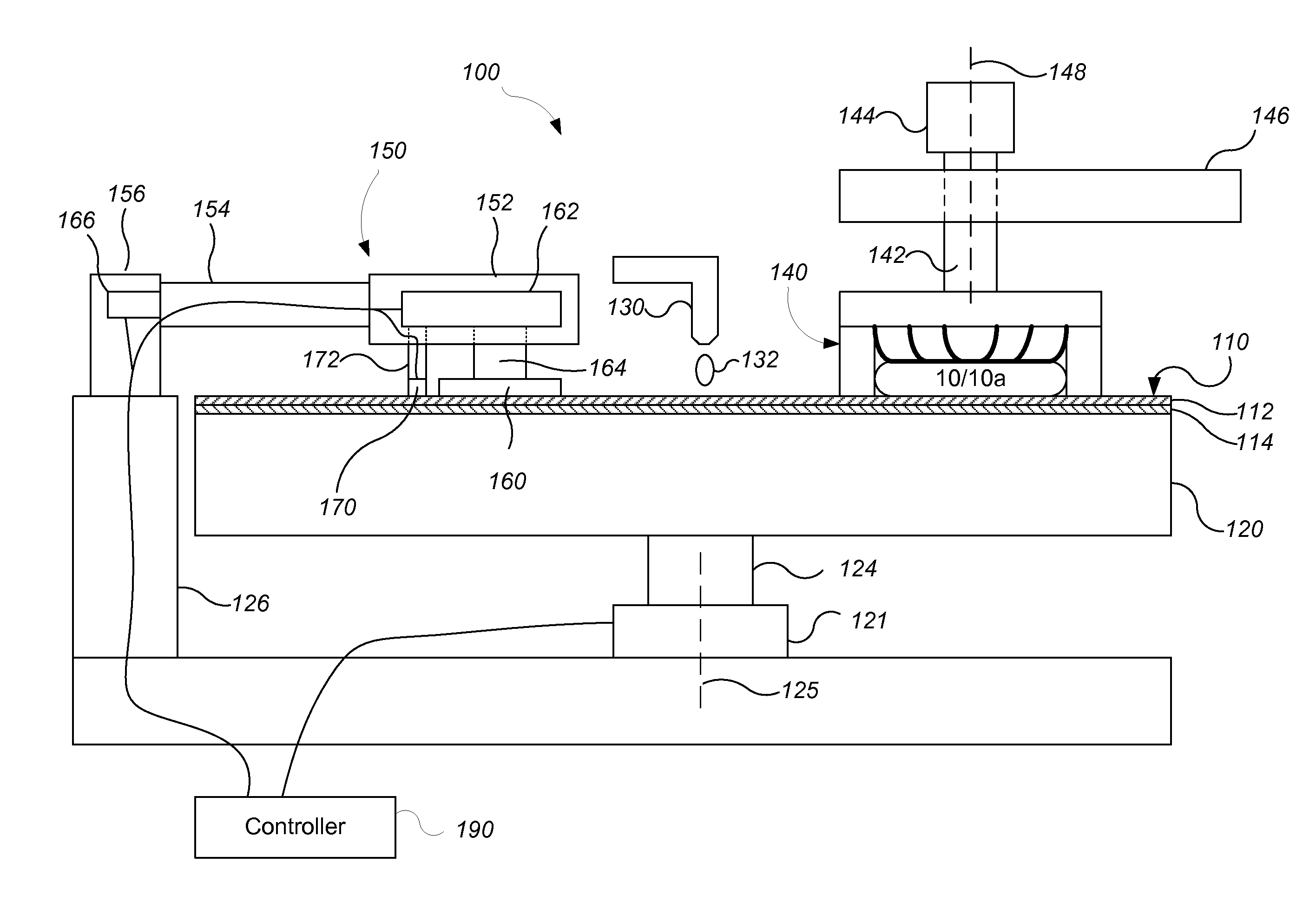
[0020]FIG. 1 illustrates an example of a polishing apparatus 100. The polishing apparatus 100 includes a rotatable disk-shaped platen 120 on which a polishing pad 110 is situated. The platen is operable to rotate about an axis 125. For example, a motor 121 can turn a drive shaft 124 to rotate the platen 120. The polishing pad 110 can be detachably secured to the platen 120, for example, by a layer of adhesive. The polishing pad 110 can be a two-layer polishing pad with an outer polishing layer 112 and a softer backing layer 114.

[0021]The polishing apparatus 100 can include a combined slurry / rinse arm 130. During polishing, the arm 130 is operable to dispense a polishing liquid 132, such as a slurry, onto the polishing pad 110. While only one slurry / rinse arm 130 is shown, additional nozzles, such as one or more dedicated slurry arms per carrier head, can be used.

[0022]The polishing apparatus 100 can further include a carrier head 140. The carrier head 140 may be operable to hold a s...


PUM

PropertyMeasurementUnit
Timeaaaaaaaaaa
Thicknessaaaaaaaaaa
Pressureaaaaaaaaaa

Abstract

A conditioning process includes rotating a polishing pad about an axis of rotation, conditioning the polishing pad by sweeping an abrasive disk in a path across a surface of the polishing pad between an inner radial distance from the axis of rotation and an outer radial distance from the axis of rotation, sweeping a sensor across the polishing pad while conditioning the polishing pad, measuring a thickness of the polishing pad at a plurality of positions between the inner radial distance and the outer radial distance with the sensor, and adjusting at least one of a dwell time or a pressure of the abrasive disk against the polishing pad for a portion of the path based on measurements of the thickness by the sensor such that the polishing pad wears to a more uniform thickness than without such adjustment.

Description

TECHNICAL FIELD The present disclosure relates to control of conditioning during chemical mechanical polishing.BACKGROUND[0001]An integrated circuit is typically formed on a substrate by the sequential deposition of conductive, semiconductive, or insulative layers on a silicon wafer. One fabrication step involves depositing a filler layer over a non-planar surface and planarizing the filler layer. For certain applications, the filler layer is planarized until the top surface of a patterned layer is exposed. A conductive filler layer, for example, can be deposited on a patterned insulative layer to fill the trenches or holes in the insulative layer. After planarization, the portions of the conductive layer remaining between the raised pattern of the insulative layer form vias, plugs, and lines that provide conductive paths between thin film circuits on the substrate. For other applications, such as oxide polishing, the filler layer is planarized until a predetermined thickness is lef...

Claims


Application Information

Patent Timeline
IPC IPC(8): B24B53/02B24B1/00
CPCB24B37/042B24B53/017B24B49/18B24B49/105G01B7/107
Inventor NANGOY, ROY C.CHEN, HUNG CHIHCHANG, SHOU-SUNGRONDUM, ERIK S.DESHPANDE, SAMEER
Owner APPLIED MATERIALS INC
Why Eureka
Try Eureka