Exhaust gas treatment device for an oxygen combustion system

Inactive Publication Date: 2012-11-01
MITSUBISHI HITACHIPOWER SYST LTD
View PDF11 Cites 23 Cited by
  • Summary
  • Abstract
  • Description
  • Claims
  • Application Information

AI Technical Summary

Benefits of technology

[0049]According to the present invention, when the exhaust gas temperature is set to be not greater than the acid dew point of SO3 and not lower than the water dew drop by the heat-recovery heat exchanger, SO3 in the exhaust gas can be highly efficiently removed together with ash. Further, since heat recovered by the heat-recovery heat exchanger reheats the exhaust gas circulation unit using the reheating heat exchanger, low-temperature corrosion of the pipes in the exhaust gas circulation unit and others can be avoided. Furthermore, when the alkaline additive is added with concentration, which causes a reaction and is equivalent to SO3 concentration in the gas at the outlet of the denitration device, it is possible to prevent corrosion of the heat-recovery heat exchanger or its pipes, the dust-collection device, and others.
[0050]Furthermore, when the water elimination device is provided on the upstream side of the reheating heat exchanger and the moisture content is reduced, the aid dew point of SO3 is reduced, and hence an effect of avoiding the low-temperature corrosion of the pipes in the exhaust gas circulation unit and others can be obtained. Moreover, since a part of the gas in the exhaust gas circulation unit having the reduced SO3 concentration is supplied to the mill, corrosion of the mill or a reduction in fluidity and combustibility of the pulverized coal in the outlet pipes can be avoided.
[0051]According to the invention defined in the first

Problems solved by technology

Since the oxygen combustion method has an exhaust gas composition greatly different from that of a conventional method (an air combustion method), points such as corrosion, ash clogging, and others of pipes or fans in an exhaust gas circulation unit due to an increase in concentration of SO3 must be taken into considerations, and development of an exhaust gas treatment device appropriate for the oxygen combustion method is also an important issue.
The conventional technology based on the oxygen combustion method or the configuration disclosed in Patent Document 3 do not pay attention to a fact that SO3 concentration or moisture concentra

Method used


Image

  • Exhaust gas treatment device for an oxygen combustion system
  • Exhaust gas treatment device for an oxygen combustion system
  • Exhaust gas treatment device for an oxygen combustion system

Examples


embodiment 1

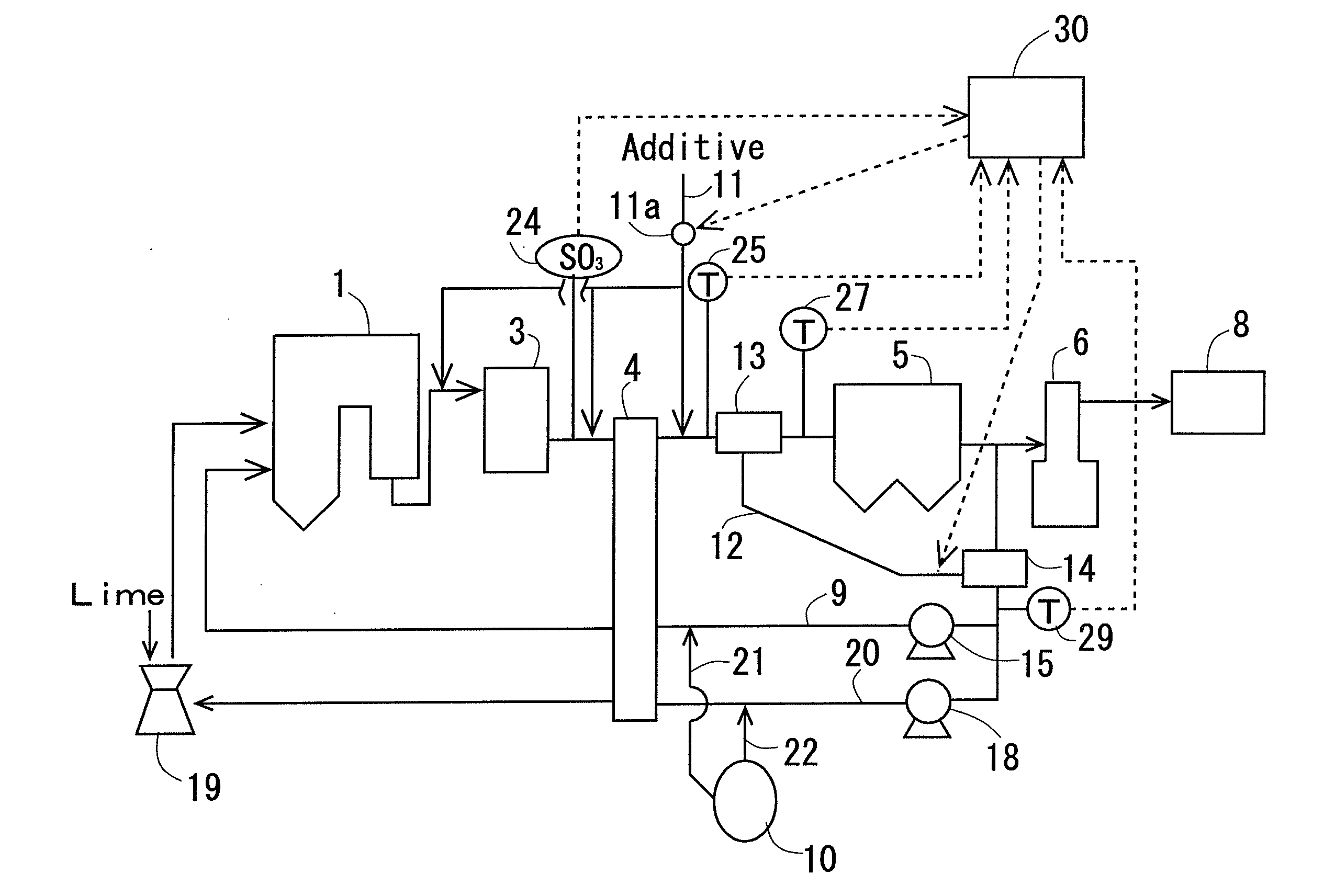
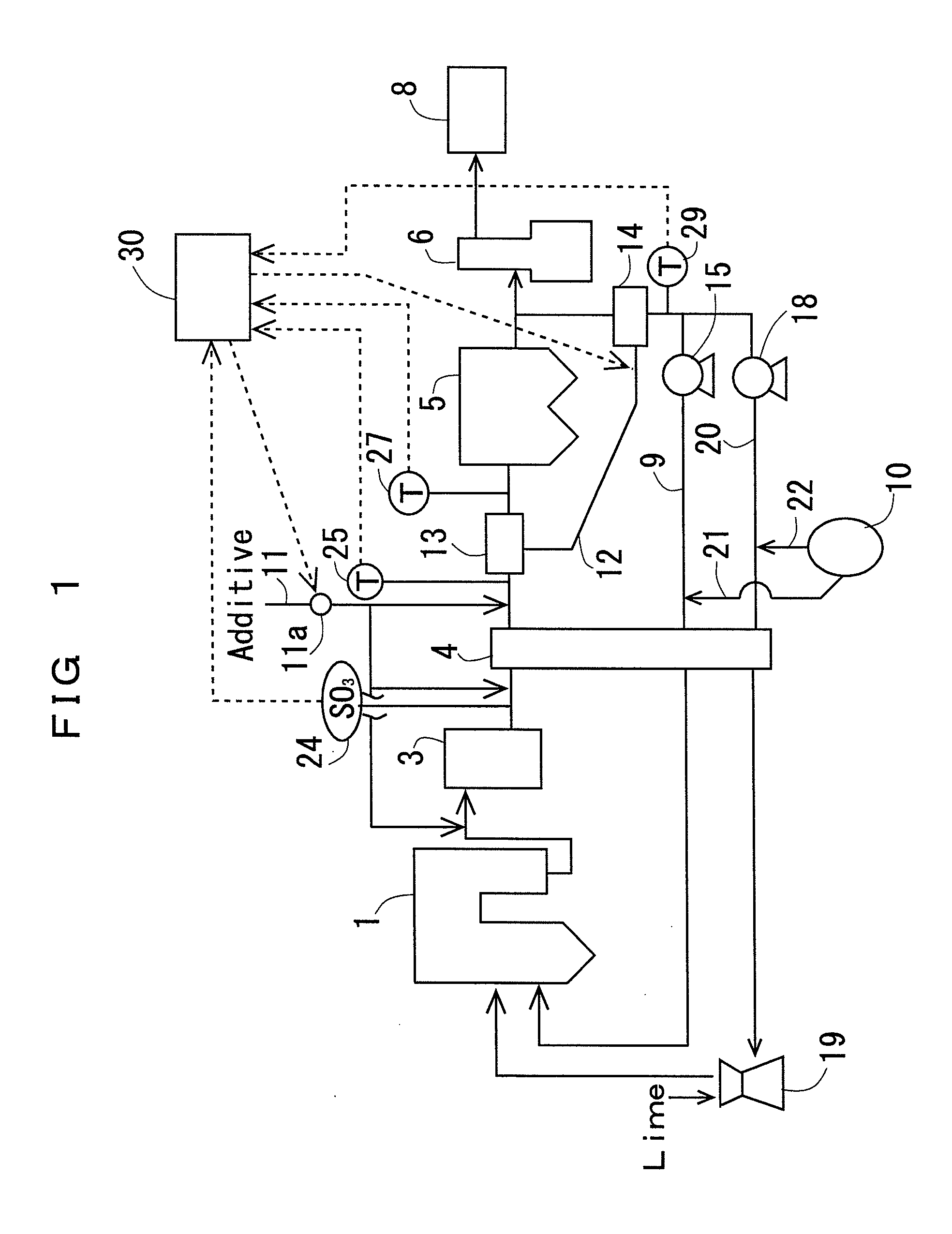
[0065]Embodiment 1 according to the present invention will now be described with reference to the drawings. FIG. 1 shows an overall configuration of an exhaust gas treatment device having a first circulation line 9 and a second circulation line 20 provided on the upstream side of a desulfurization device 6.

[0066]This exhaust gas treatment device is mainly constituted of an exhaust gas treatment unit in which a mill 19 that pulverizes coal as fuel, a boiler 1 to which the coal pulverized by the mill 19 is supplied, a denitration device 3 that treats a nitrogen oxide in an exhaust gas generated from the boiler 1, an air preheater 4 that heats combustion air used in the boiler 1 by an outlet exhaust gas of the denitration device 3, a heat-recovery heat exchanger 13 that recovers heat from the exhaust gas discharged from the air preheater 4, a dust-collection device 5 that removes smoke dust and others in the outlet exhaust gas of the heat-recovery heat exchanger 13, a desulfurization d...

embodiment 2

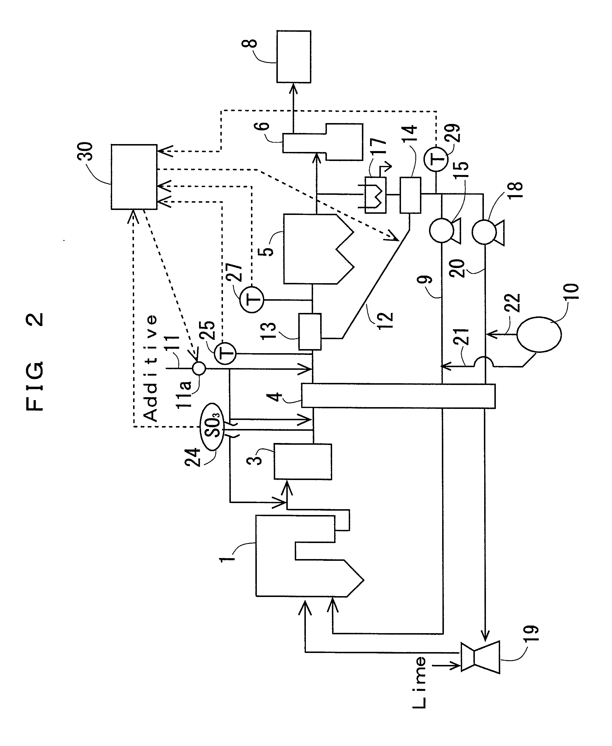
[0087]FIG. 2 shows an overall configuration of an exhaust gas treatment device according to Embodiment 2 of the present invention. The exhaust gas treatment device in FIG. 2 is different form the exhaust gas treatment device in FIG. 1 (Embodiment 1) in that a water elimination device 17 is disposed on the upstream side of a reheating heat exchanger 14.

[0088]This exhaust gas treatment device is mainly constituted of an exhaust gas treatment unit in which a mill 19 that pulverizes coal as fuel, a boiler 1 to which the coal pulverized by the mill 19 is supplied, a denitration device 3 that treats a nitrogen oxide in an exhaust gas generated from the boiler 1, an air preheater 4 that heats combustion air used in the boiler 1 by the outlet exhaust gas of the denitration device 3, a heat-recovery heat exchanger 13 that recovers heat from the exhaust gas discharged from the air preheater 4, a dust-collection device 5 that removes smoke dust and others in the outlet exhaust gas of the heat-...

embodiment 3

[0094]FIG. 3 shows an overall configuration of an exhaust gas treatment device according to Embodiment 3 of the present invention. The exhaust gas treatment device in FIG. 3 is different from the exhaust gas treatment device in FIG. 1 (Embodiment 1) that a first circulation line 9 and a second circulation line 20 are disposed on the downstream side of a desulfurization device 6.

[0095]This exhaust gas treatment device is mainly constituted of an exhaust gas treatment unit in which a mill 19 that pulverizes coal as fuel, a boiler 1 to which the coal pulverized by the mill 19 is supplied, a denitration device 3 that treats a nitrogen oxide in an exhaust gas generated from the boiler 1, an air preheater 4 that heats combustion air used in the boiler 1 by the outlet exhaust gas of the denitration device 3, a heat-recovery heat exchanger 13 that recovers heat from the exhaust gas discharged from the air preheater 4, a dust-collection device 5 that removes smoke dust and others in the outl...


PUM

PropertyMeasurementUnit
Temperatureaaaaaaaaaa
Concentrationaaaaaaaaaa

Abstract

In an exhaust gas treatment device provided with: an exhaust gas treatment unit in which an oxygen combustion boiler 1 using coal as fuel, a denitration device 3, an air preheater 4, a dust-collection device 5, a desulfurization device 6, and a carbon dioxide recovery device 8 are sequentially arranged from the upstream side to the downstream side of an exhaust gas duct; and an exhaust gas circulation unit which branches off from the exhaust gas duct at an outlet of the dust-collection device 5 or an outlet of the desulfurization device 6 and through which the exhaust gas is preheated by the air preheater 4 and returned to the oxygen combustion boiler 1, a heat-recovery heat exchanger 13 that adjusts a gas temperature at an inlet of the dust-collection device 5 to be not greater than an acid dew point of SO3 and not lower than a water dew point is provided between the air preheater 4 and the dust-collection device 5, a reheating heat exchanger 13 that adjusts a gas temperature to be not lower than the acid dew point of SO3 is provided in the vicinity of a branch of the exhaust gas circulation unit, adjusting the gas temperature at the inlet of the dust-collection device 4 to be not greater than the acid dew point of SO3 makes it possible to prevent corrosion of pipes in the exhaust gas circulation unit and to avoid a decrease in fluidity or combustibility of the pulverized coal in the pipes in the mill.

Description

FIELD OF THE INVENTION[0001]The present invention relates to an exhaust gas treatment device that removes hazardous components in an exhaust gas of an oxygen combustion system, and more particularly to an exhaust gas treatment device appropriate to avoid corrosion, ash clogging, and others of pipes or fans in an exhaust gas circulation unit by efficiently removing a sulfur trioxide (SO3) by a dust-collection unit.DESCRIPTION OF THE RELATED ART[0002]In recent years, as one of carbon dioxide (CO2) reduction technologies for a power generator boiler, an oxygen combustion method attracts attention. Since the oxygen combustion method has an exhaust gas composition greatly different from that of a conventional method (an air combustion method), points such as corrosion, ash clogging, and others of pipes or fans in an exhaust gas circulation unit due to an increase in concentration of SO3 must be taken into considerations, and development of an exhaust gas treatment device appropriate for ...

Claims


Application Information

Patent Timeline
IPC IPC(8): B01D50/00
CPCB01D53/343Y02E20/363B01D53/504B01D53/56B01D53/62B01D53/75B01D2251/304B01D2251/306B01D2251/404B01D2251/606B01D2257/302B01D2257/404B01D2257/504F23C9/003F23J15/006F23J15/06F23J15/08F23J2215/20F23J2215/50F23J2217/10F23J2217/50F23J2219/20F23J2219/70F23L7/007Y02E20/344Y02E20/346B01D53/346B01D53/508Y02E20/30Y02E20/32Y02E20/34
Inventor MITSUI, YOSHIAKIYOSHIZAKO, HIDEHISAIMADA, NORIYUKIODA, NAOKI
Owner MITSUBISHI HITACHIPOWER SYST LTD
Why Eureka
Try Eureka