System and Method for Providing a Continuous Flow of Catalyst Into a Polyolefin Reactor

a polyolefin reactor and catalyst technology, applied in the direction of machines/engines, liquid fuel engines, positive displacement liquid engines, etc., can solve the problems of unfavorable catalyst flow, catalyst tends to non-uniformly accumulate in localized regions, and the catalyst feed system often provides undesirable non-uniform catalyst concentrations within the reactor loop, etc., to facilitate the flow of catalyst slurry, reduce work load and wear, and prevent fouling

Active Publication Date: 2012-11-01
CHEVRON PHILLIPS CHEMICAL CO LP
View PDF5 Cites 7 Cited by
  • Summary
  • Abstract
  • Description
  • Claims
  • Application Information

AI Technical Summary

Benefits of technology

[0017]Finally, in all embodiments of the system of the invention, a recycled diluent flush may be provided between the pump outlet and the reactor inlet to facilitate the flow of catalyst slurry to the reactor. Because the diluent flush is located downstream of the progressive cavity pump, there is no opportunity for pump fouling caused by polymerization of monomer impurities in the recycled diluent.
[0018]In the method of the invention, the pressure of the reservoir of catalyst slurry is preferably adjusted within a range such that (1) it is higher than that of the reactor and (2) the net pressure drop at the pump outlet is minimal to zero. The fulfillment of the first condition insures there will be no backflow of reactor effluent into the catalyst reservoir, thus preventing fouling in the pump and the reservoir, while the fulfillment of the second condition advantageously reduces the work load and wear on the progressive cavity pump and allows it to function as more of a catalyst metering device than a pump. In practice, such a balance has been achieved when the pressure of the catalyst slurry reservoir is adjusted to a level between about 5 to 25 psi (or 0.34 to 1.72 bars) higher than the internal pressure of the reactor.
[0019]Next, the outlet of the reservoir is opened and the progressive cavity pump is actuated. The resulting draw-down and flow of catalyst diluent through the interstices of the particles of catalyst dramatically reduces the viscosity of the mud-like catalyst and initiates a continuous flow of catalyst slurry into the reactor.

Problems solved by technology

Applicants have observed that the dosing feeder often provides undesirably non-uniform concentrations of catalyst within the reactor loop during the operation of the reactor.
In such a case, the catalyst tends to non-uniformly accumulate in localized regions of the circulating polymer slurry.
Regions with high concentrations of catalyst will thicken and overheat and create large particles and strings of polymer that can foul the guide vanes and pumps in the reactor that circulate the effluent.
Alternatively, the inconsistent density of slurry within the reactor can cause pumping instability and ultimately loss of pumping.
Loss of pumping can cause reactor plugging and result in an extended down time.
Moreover, irregularities in the flow of the viscous, mud-like catalyst from the gravity outlet of the mud-pot to the dosing chamber can cause variations in the amount of catalyst contained in the slugs, thus causing variations in the over-all polymerization rate.
The resulting inconsistencies in polymerization rates can result in production losses, particularly when attempting to run the reactor at maximum rates.
Finally, the flow of diluent to such feeders that is necessary to flush the catalyst slurry out of the dosing chamber and into the reactor sometimes causes fouling problems which can render the dosing feeder inoperative.
Such fouling stems from the fact that the diluent used is typically recycled from the reactor due to the high flow rates of about 5 gallons (or 19 liters) per minute.
Because such recycled diluent sometimes includes small amounts of monomer (examples are ethylene and / or hexene) as a result of an upset of one of the plant's distillation columns, enough polymerization can take place within the dosing feeder mechanism to “glue” its moving parts together, necessitating expensive plant downtime to effect repairs.
However, it is a capital intensive system requiring an agitated slurry vessel and associated mixing mechanisms and control systems.
Also, because the pressure within the slurry vessel is typically less than the pressure within the reactor for such a feeder to be practical, slurry feeders are vulnerable to occurrences of the reactor effluent back-flowing into the slurry feed system.
Such back-flowing in turn can cause the feeder or other parts of the feed system to become plugged and fouled.
Other shortcomings include reliability problems associated with the agitator and pump, as well as the concentration of catalyst in the flow stream being too dilute to be accurately measured with conventional mass flow meters.
Moreover, the use of a piston-type pump in such slurry feeders still delivers the slurry catalyst in pulses which result in some inhomogeneity in the distribution of catalyst throughout the reactor.

Method used


Image

  • System and Method for Providing a Continuous Flow of Catalyst Into a Polyolefin Reactor
  • System and Method for Providing a Continuous Flow of Catalyst Into a Polyolefin Reactor
  • System and Method for Providing a Continuous Flow of Catalyst Into a Polyolefin Reactor

Examples


Embodiment Construction

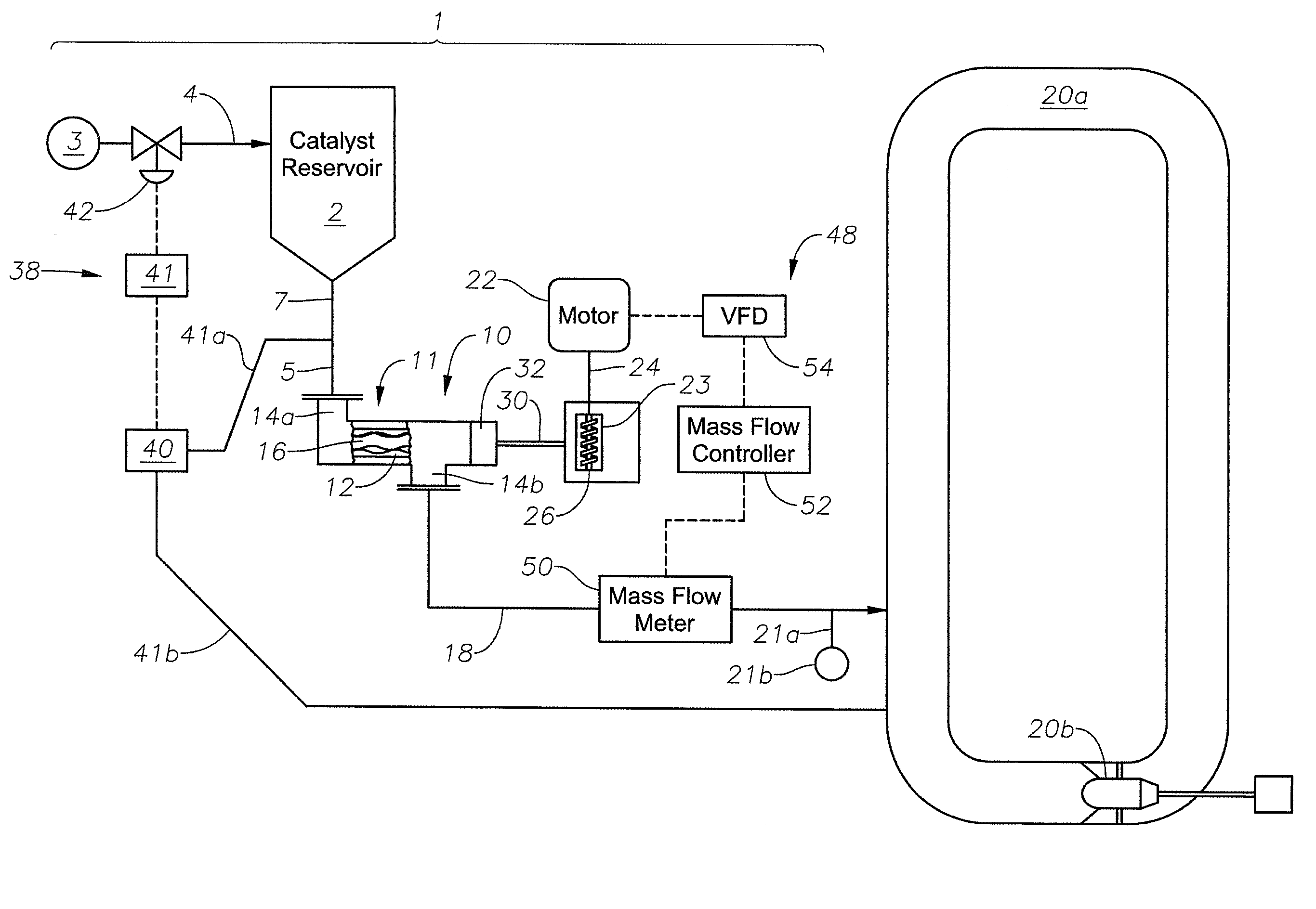
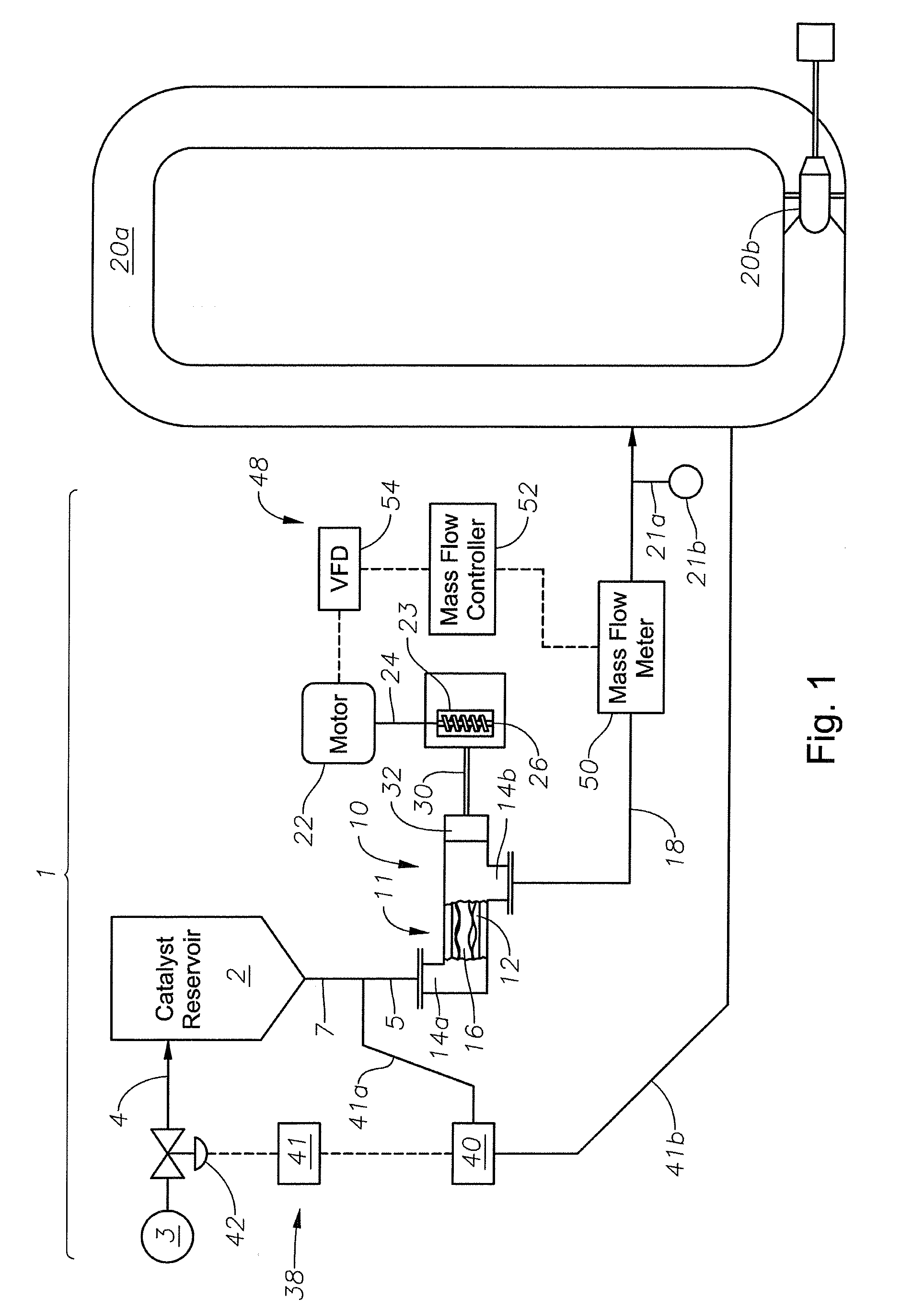
[0027]With reference now to FIG. 1, the catalyst feed system 1 of the invention includes a reservoir 2 for containing a supply of mud-like catalyst slurry. Reservoir 2 is connected to a source 3 of pressurized diluent via a conduit 4. Reservoir 2 further has an outlet 5 located at the distal end of a discharge conduit 7. The system 1 further includes a progressive cavity pump 10 having a stator and rotor assembly 11. The stator 12 of the assembly 11 includes an inlet 14a connected to the outlet 5 of the reservoir 3, and a discharge outlet 14b. A rotor 16 rotates within the inner diameter of the stator 12 to pump catalyst slurry through the outlet 14b and the outlet pipe 18 to one of the loops 20a of a polyolefin reactor. Reactor loop 20a includes a pump 20b for circulating reactor effluent during the manufacture of a polymer. A flush line 21 a connected to a source of recycled, pressurized diluent 21b is connected to the outlet pipe 18 for expediting the flow of catalyst slurry to t...


PUM

PropertyMeasurementUnit
diameteraaaaaaaaaa
pressureaaaaaaaaaa
internal pressureaaaaaaaaaa

Abstract

Both a catalyst feed system and a method are provided for providing a flow, of a mud-like catalyst slurry into a polyolefin reactor. The system includes a pressurized reservoir of the catalyst having an outlet, and a progressive cavity pump including a stator and a rotor. The pump stator has an inlet connected to the reservoir outlet, and an outlet leading to the polyolefin reactor. In operation, the reservoir is first pressurized to a level a little higher than the pressure of the reactor. The outlet of the reservoir is opened and the progressive cavity pump is actuated. The pressure drop generated across the catalyst slurry contained in the reservoir by the pump causes the slurry diluent to flow between the interstices of the particles of catalyst. The thick, mud-like catalyst slurry is quickly transformed into a much less viscous, syrup-like slurry that flows from the reservoir outlet to the inlet of the pump stator. The progressive cavity pump then continuously conveys the catalyst through the stator outlet and into the reactor.

Description

FIELD OF THE INVENTION[0001]This invention generally relates to catalyst feed systems for polyolefin reactors, and is specifically concerned with a system and method for providing a continuous flow of particulate catalyst to such a reactor by the use of a progressive cavity pump.BACKGROUND OF THE INVENTION[0002]Polyolefin reactors are used for the commercial production of a number of polyolefin compounds, such as polyethylene. In such reactors, for example loop-type reactors, the monomer and optional comonomers to be polymerized are mixed with a diluent such as isobutane and subjected to heat and pressure while circulating through the loops of the reactor. To initiate the polymerization process, a catalyst is introduced into the circulating mixture of monomers and diluent. Once polymerization is initiated, an effluent is formed comprising a slurry of particulate polymer solids suspended in the reaction diluent and unreacted monomers.[0003]Many of the catalysts used to initiate polym...

Claims


Application Information

Patent Timeline
Patent Type & Authority Applications(United States)
IPC IPC(8): B01J19/00F04B53/00
CPCB01J8/002B01J19/2435B01J2208/00752C08F10/00F04C2/1071F04C15/0038F04C11/003C08F2/00
Inventor DEPIERRI, ROBERT G.DABADIE, J. CHARLESCOOK, III, N. FRANK
Owner CHEVRON PHILLIPS CHEMICAL CO LP
Why Eureka
Try Eureka