Photovoltaic element with increased long-term stability

a photovoltaic element and long-term stability technology, applied in the field of photovoltaic elements, can solve the problems of high cost of technology, general limited proportion of light which can be used by dyes, and stability problems, and achieve the effects of preventing recombination, good suitability, and facilitating the regeneration of dyes

Inactive Publication Date: 2012-11-08
BASF AG
View PDF7 Cites 25 Cited by
  • Summary
  • Abstract
  • Description
  • Claims
  • Application Information

AI Technical Summary

Benefits of technology

[0137]The rylene derivatives I can be fixed easily and in a permanent manner to the n-semiconductive metal oxide film. The bonding is effected via the anhydride function (x1) or the carboxyl groups —COOH or —COO— formed in situ, or via the acid groups A present in the imide or condensate radicals ((x2) or (x3)). The rylene derivatives I described in DE 10 2005 053 995 A1 have good suitability for use in dye-sensitized solar cells in the context of the present invention.
[0138]It is particularly preferred when the dyes, at one end of the molecule, have an anchor group which enables the fixing thereof to the n-semiconductor film. At the other end of the molecule, the dyes preferably comprise electron donors Y which facilitate the regeneration of the dye after the electron has been released to the n-semiconductor, and also prevent recombination with electrons already released to the semiconductor.

Problems solved by technology

Even though silicon-based solar cells now dominate the market on Earth, this technology still remains costly.
However, the dye solar cell produced with liquid electrolyte in many cases suffers from nonoptimal sealing, which can lead to stability problems.
One disadvantage of the dye solar cell is that the proportion of light which can be used by the dye is generally limited by the energetic distance between the Fermi energies of the n- and p-conductors used.
The photovoltage is generally also limited by this distance.
In addition, dye solar cells generally have to be comparatively thin due to the charge transport required (for example 1-2.5 micrometers), and so the exploitation of the incident light is generally not optimal.
A further known technical challenge associated with dye solar cells is that of the long-term stability thereof.
However, dye solar cells known from the prior art in many cases have an efficiency which declines significantly with time.
There are thus conflicting aims, since illumination of the dye solar cells is required on the one hand for generation of electrical energy, but, at the same time, specifically this illumination contributes to degradation of the dye solar cells.

Method used


Image

  • Photovoltaic element with increased long-term stability
  • Photovoltaic element with increased long-term stability
  • Photovoltaic element with increased long-term stability

Examples


examples 2 to 5

Photovoltaic Elements with Spiro-MeOTAD as Organic p-Semiconductor and Various Longpass Filters

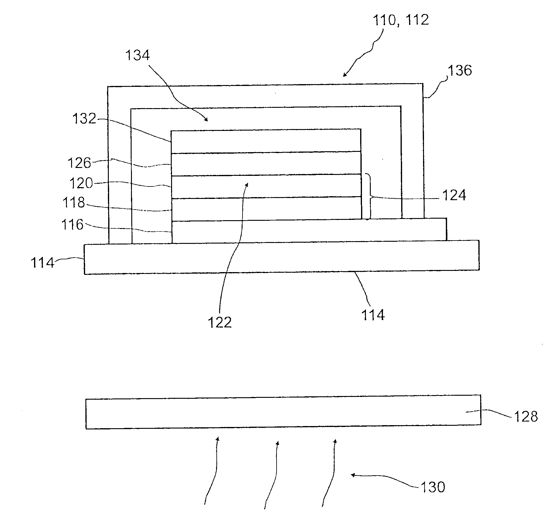
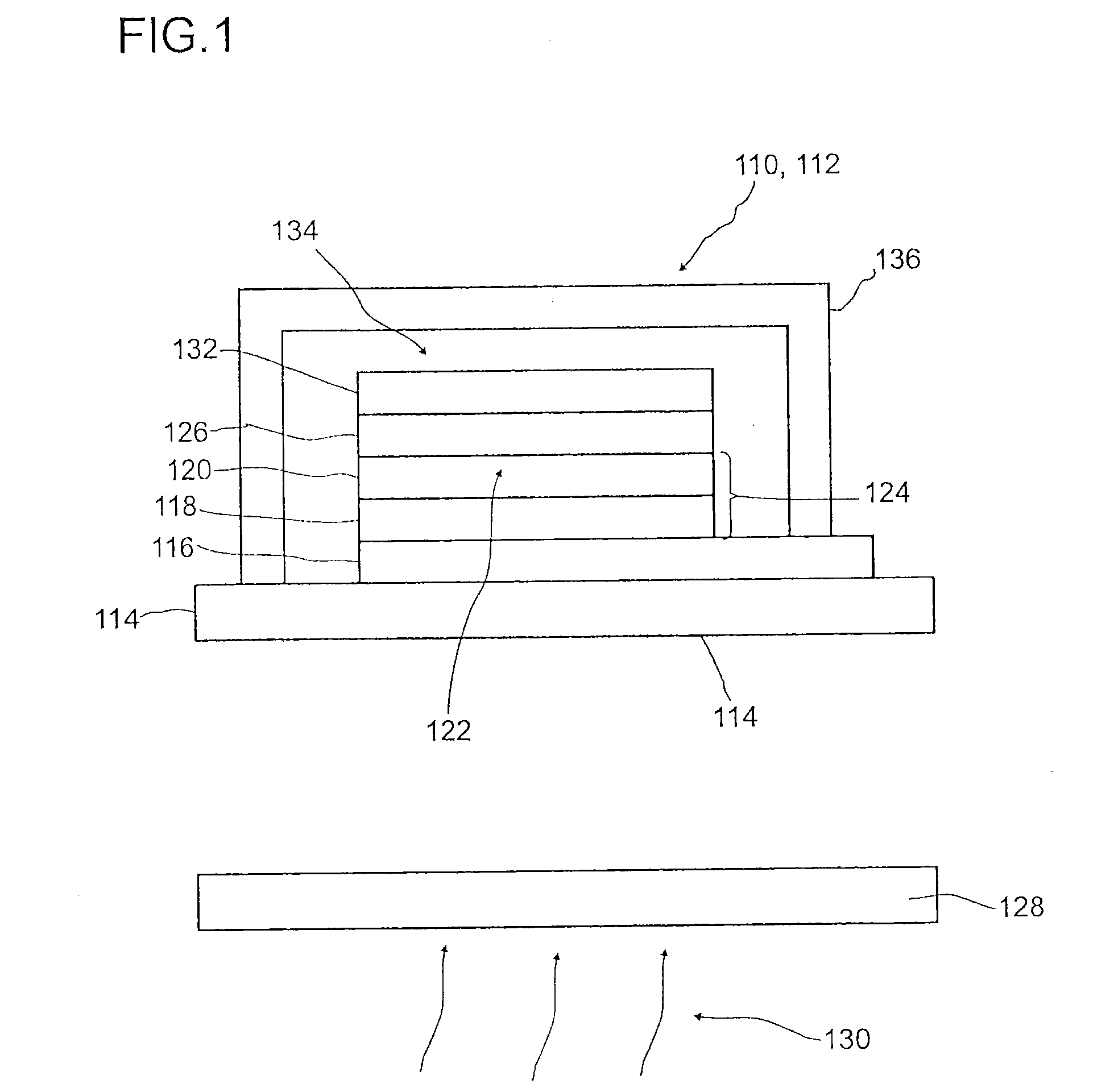
[0261]As inventive working examples (examples 2 to 5), four photovoltaic elements were first produced according to the above-described example 1. In addition, these photovoltaic elements, however, were each provided with a longpass filter on the non-FTO-coated side of the glass substrate.

[0262]The longpass filters used in this case were commercially available glass longpass filters of the LCGG-X-2X2 type from LASER COMPONENTS GmbH in 82140 Olching, Germany, X designating the characteristic edge wavelength λLP, namely:[0263]Example 2: LCGG-385-2X2, λLP=385 nm[0264]Example 3: LCGG-420-2X2, λLP=420 nm[0265]Example 4: LCGG-435-2X2, λLP=435 nm[0266]Example 5: LCGG-450-2X2, λLP=450 nm

[0267]These filter types are UV filters with their own glass substrate, which has been placed directly onto the glass substrate of the photovoltaic element. However, another structure which is possible in principle ...

example 6

Method for Production of the UV / VIS Protective Varnish Layers

[0283]In order to test the optical efficacy of varnishes as a longpass filter 128, UV protection layers were first produced in the form of varnish layers on glass substrates. To produce the protective layers, the commercially available HS (high solids) clearcoat, scratch-resistant VOC from Glasurit was used. It likewise comprises the diluent and hardener components. To produce varnish layers on the glass substrates, the varnish was applied by means of a spin coater at 1000 rpm to 25 mm×25 mm front-side cell cover glasses for 30 sec. Subsequently, the cells were heat-treated at 60° C. for 2 h.

example 6.1

UV Protection Varnish Comprising the UV Absorbers Carboprotect and Tinuvin 400 (Full UV)

[0284]In addition, samples were produced analogously to example 6, in which commercial UV absorbers were added to the varnish as the matrix material. Stirred into a mixture of: 2.5 g of clearcoat, 0.41 g of diluent and 1.25 g of hardener were in each case 78 mg or 39 mg of commercial UV absorber Carboprotect Xymara or Tinuvin 400.

[0285]300 microliters of this solution was applied with a spin coater at 1000 rpm to 25 mm×25 mm front-side cell cover glasses for 30 sec. Subsequently, the cells were heat-treated at 60° C. for 2 h.


PUM

PropertyMeasurementUnit
wavelengthsaaaaaaaaaa
wavelengthaaaaaaaaaa
wavelengthsaaaaaaaaaa

Abstract

A photovoltaic element for conversion of electromagnetic radiation to electrical energy, having at least one first electrode, at least one n-semiconductive metal oxide, at least one dye for absorption of electromagnetic radiation, at least one organic hole conductor material, and at least one second electrode. The organic hole conductor material has an absorption spectrum which has a maximum in the ultraviolet or blue spectral region and, toward higher wavelengths, an absorption edge declining with wavelength and having a characteristic wavelength λHTL. A decadic absorbance of the hole conductor material at a wavelength λHTL within the declining absorption edge is 0.3. The photovoltaic element includes a longpass filter, which has a transmission edge rising with wavelength and having a characteristic wavelength λLP. A transmission of the longpass filter at λLP is 50% of a maximum transmission of the longpass filter, where λHTL−30 nm≦λLP≦λHTL+30 nm.

Description

FIELD OF THE INVENTION[0001]The invention relates to a photovoltaic element for conversion of electromagnetic radiation to electrical energy, to a process for production of a photovoltaic element for conversion of electromagnetic radiation to electrical energy and to a process for selection of a longpass filter for use in a photovoltaic element for conversion of electromagnetic radiation to electrical energy. Such photovoltaic elements and processes are used to convert electromagnetic radiation, especially sunlight, to electrical energy. More particularly, the invention can be applied to dye solar cells.PRIOR ART[0002]The direct conversion of solar energy to electrical energy in solar cells is based generally on what is called the “internal photoeffect” of a semiconductor material, i.e. the production of electron-hole pairs by absorption of photons and the separation of the negative and positive charge carriers at a p-n junction or a Schottky contact. In this way, a photovoltage is ...

Claims


Application Information

Patent Timeline
Patent Type & Authority Applications(United States)
IPC IPC(8): H01L31/0232H01L31/18C09D133/08H01L51/46
CPCH01L51/0053H01L51/0059Y02E10/549H01L51/4226H01G9/2018H01L51/0067H10K85/621H10K85/631H10K85/654H10K30/151
Inventor BRUDER, INGMARSENS, RUDIGERGROB, MARKUSSCHULZE TILLING, URSULA
Owner BASF AG
Why Eureka
Try Eureka