

Organic el element having cathode buffer layer
- Summary
- Abstract
- Description
- Claims
- Application Information
AI Technical Summary
Benefits of technology
Problems solved by technology
Method used
Image

Examples
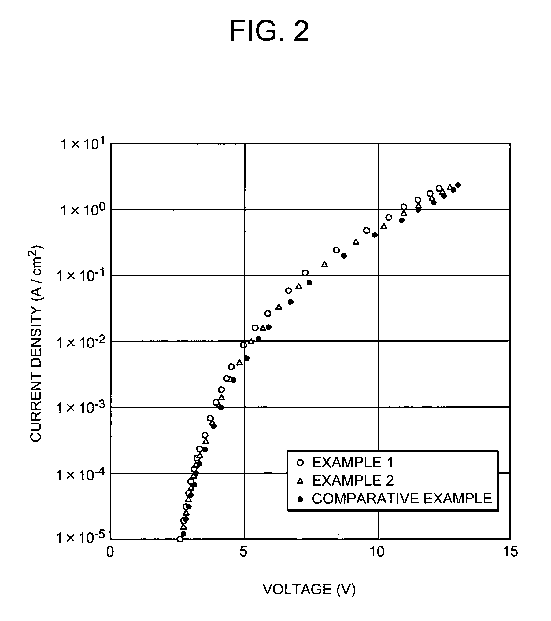
example 1
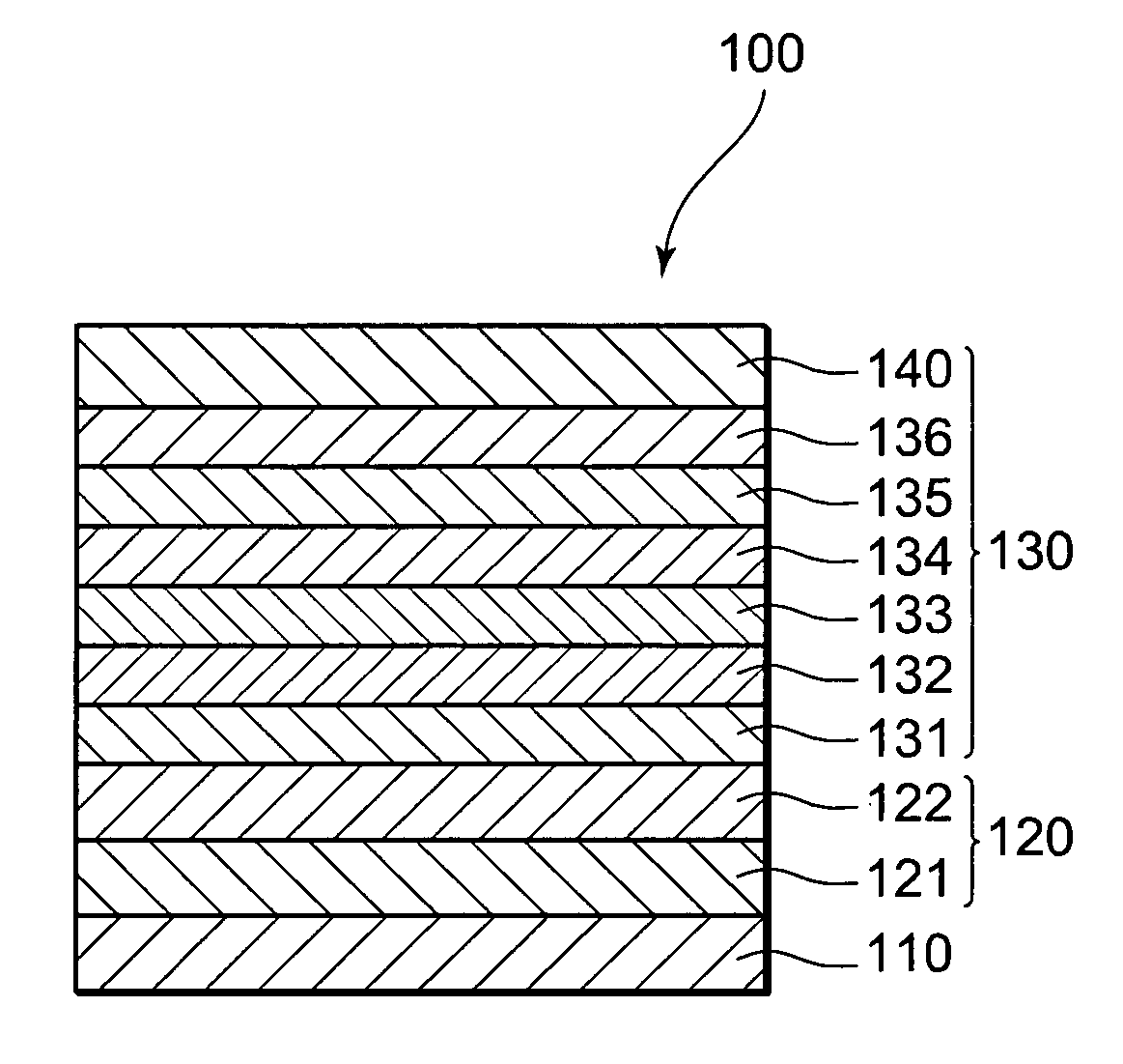
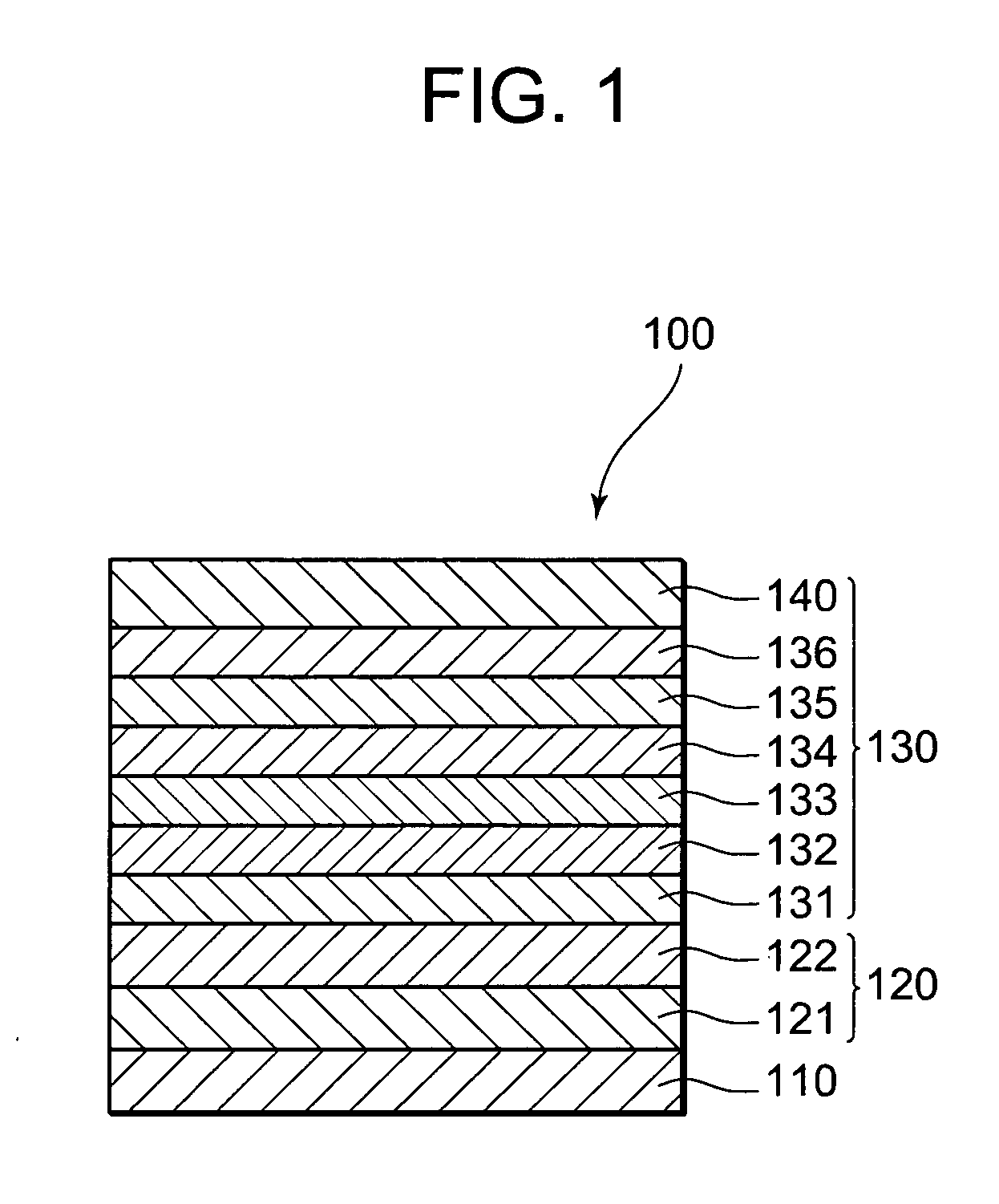
[0069]This example is an example of an organic EL element having cathode 120 made of Ag and IZO, cathode buffer layer 131, electron injection transport layer 132, light-emitting layer 133, hole transport layer 134, hole injection transport layer 135, anode buffer layer 136 and anode 140 formed in that order on substrate 110.
[0070]An Ag film 100 nm thick was formed by DC magnetron sputtering on glass substrate 110 (length 50 mm×width 50 mm×thickness 0.7 mm; Corning 1737 glass). An IZO film 110 nm thick was then formed by DC magnetron sputtering (target: In2O3+10 wt % ZnO, discharge gas: Ar+0.5% O2 discharge pressure: 0.3 Pa, discharge power: 1.45 W / cm2, substrate transport rate 162 mm / min) on the upper surface of the Ag film. Next, the laminate of Ag film and IZO film was worked in 2 mm-wide stripes by photolithography to form reflecting layer 121 having a width of 2 mm and transmitting layer 122 having a width of 2 mm, to obtain cathode 120.
[0071]Organic EL layer 130 was then formed...
example 2
[0076]An organic EL element was produced by following the procedures used in Example 1, except that the thickness of cathode buffer layer 131 was changed to 50 nm.
PUM
 Abstract
Description
Claims
Application Information