

Magnetic induction system and operating method for same incorporation by reference
- Summary
- Abstract
- Description
- Claims
- Application Information
AI Technical Summary
Benefits of technology
Problems solved by technology
Method used
Image

Examples
examples
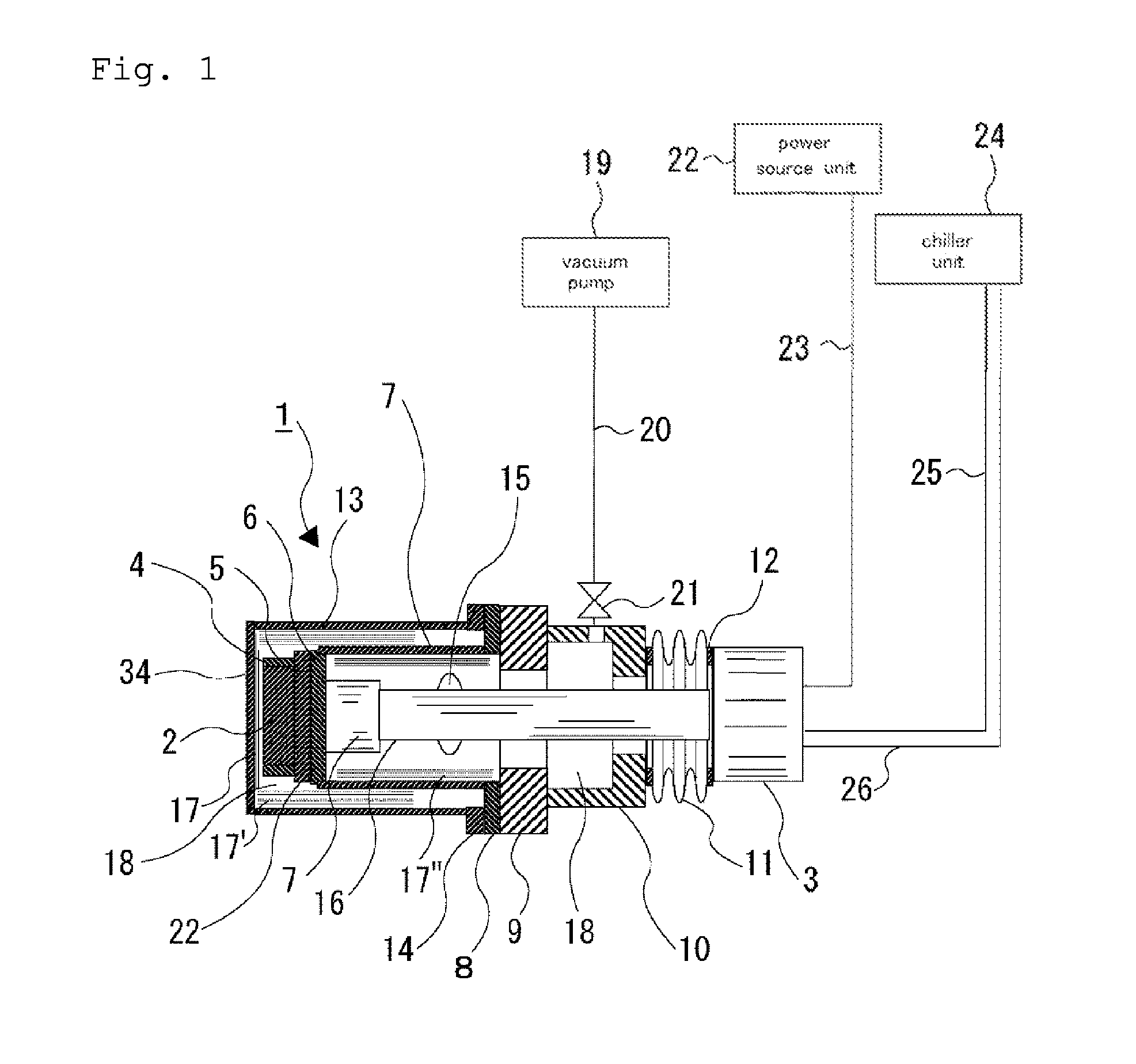
[0068]The superconductive bulk magnet 2 included in the magnetic field generation means 1 as shown in FIG. 1 comprises the following constituent elements. As the magnetic field generation means 1, for example, shown is a configuration where a YBCO-base superconductive bulk body is used, and the superconductive bulk body is directly cooled with the compressor (now shown)-integrated starling type small-size refrigerator 3 using an operating gas of helium or any other than helium gas such as nitrogen or the like. The outer periphery of the superconductive bulk body is integrated with a stainless or aluminium-made ring 4 with an adhesive or the like so that the superconductive bulk body is prevented from being cracked owing to the magnetic force thereof in magnetizing the bulk body. The superconductive bulk body and the ring 4 are thermally integrated with the heat-transfer flange 5 of copper or aluminium, with an adhesive or the like, and the heat-transfer flange 5 and the heat-transfe...
example of
Production of Superconductive Bulk Magnet
[0097]For realizing the apparatus of the invention, a superconductive bulk magnet excellent in directionality and capable of generating a strong magnetic field at high temperature is needed. For realizing the system, a bulk superconductor having a high critical temperature, excellent in critical current in a high-temperature high-intensity magnetic field and excellent in mechanical characteristics and thermal stability is needed. Examples of producing superconductive bulk bodies suitable to the system are shown below. Table 1 shows a summary of production examples for superconductive bulk bodies.
TABLE 1(Magnet Production Examples)NumberShape-Trappedof AlMemory Alloy-Wood MetalMagneticMagnet CompositionRodsMade RingInfiltrationFieldProduction(Nd,Eu,Gd)—Ba—Cu—O6Fe—Mn—SiPb—Bi—Sn4 TExample 1(surface)Production(Nd,Eu,Gd)—Ba—Cu—O6——3.5 TExample 2(surface)Production(Nd,Eu,Gd)—Ba—Cu—O———2 TExample 3(surface)ProductionGd—Ba—Cu—O6Fe—Mn—SiPb—Bi—Sn3 TExa...
production example 1
[0098]A powder of (Nd, Eu, Gd) Ba2Cu3Oy (where 6.8≦y≦7.0) and a powder of (Nd, Eu, Gd)2BaCuO5, in which the mixing ratio of Nd, Eu and Gd was 1 / 1 / 1, were prepared, and these compounds were weighed at a ratio of 4 / 1, and after 0.5% by weight of Pt was added thereto, these were well mixed (step 1001). Subsequently, this was shaped into a pellet having a diameter of 42 mm and a thickness of 15 mm under a hydrostatic pressure of 2000 MPa (step 1002). The pellet was partially sintered by heating in air at 900° C. for 1 hour (step 1003). Next, 6 artificial holes each having a diameter of 2 mm were formed at regular intervals along the circumference spaced by 20 mm from the center of the sintered body, using a carbide drill (step 1004). Next, at the bottom of an Al2O3-made crucible having a diameter of 50 mm, a pellet formed of an Nd2O3 powder and having a diameter of 45 mm and a thickness of 2 mm was put, and a pellet formed of a BaCuO2 powder and having a diameter of 45 mm and a thicknes...
PUM
 Abstract
Description
Claims
Application Information