System and Method for Hybrid Radiofrequency Labeling for Magnetic Resonance Imaging

a magnetic resonance imaging and radiofrequency labeling technology, applied in the field of magnetic resonance imaging system and method, can solve the problems of not always feasible to determine if a stenosis, the inability to provide accurate or sufficient hemodynamic information, and the significant financial cost of contrast agents that must be administered to enhance the blood vessel, etc., and achieve the effect of increasing the number of snr

Active Publication Date: 2012-11-22
NORTHSHORE UNIV HEALTHSYST
View PDF9 Cites 12 Cited by
  • Summary
  • Abstract
  • Description
  • Claims
  • Application Information

AI Technical Summary

Benefits of technology

[0014]The present invention provides a system and method for producing an angiogram with a magnetic resonance imaging (MRI) system that combines pulsed and continuous (or pseudo-continuous) radiofrequency (RF) labeling preparations to yield increased SNR over traditional pulsed RF labeling techniques and controls SAR and other undesirable constraints with flexibility not provided by continuous (or pseu

Problems solved by technology

While CE MRA is a highly effective means for noninvasively evaluating the vascular and physiological performance, for example, by studying perfusion, the technique suffers from several additional drawbacks.
First, the contrast agent that must be administered to enhance the blood vessel carries a significant financial cost.
Second, contrast agents such as gadolinium have recently been shown to be causative of a debilitating and potentially fatal disorder called nephrogenic systemic fibrosis (NSF).
Third, CE MRA, may not provide accurate or sufficient hemodynamic information, so that it is not always feasible to determine if a stenosis is hemodynamically significant or to asses the perfusion in a clinically useful manner.
To perform PC MRA pulse sequences, a substantial scan time is generally required and the operator must set a velocity-encoding sensitivity, which var

Method used


Image

  • System and Method for Hybrid Radiofrequency Labeling for Magnetic Resonance Imaging
  • System and Method for Hybrid Radiofrequency Labeling for Magnetic Resonance Imaging
  • System and Method for Hybrid Radiofrequency Labeling for Magnetic Resonance Imaging

Examples


Embodiment Construction

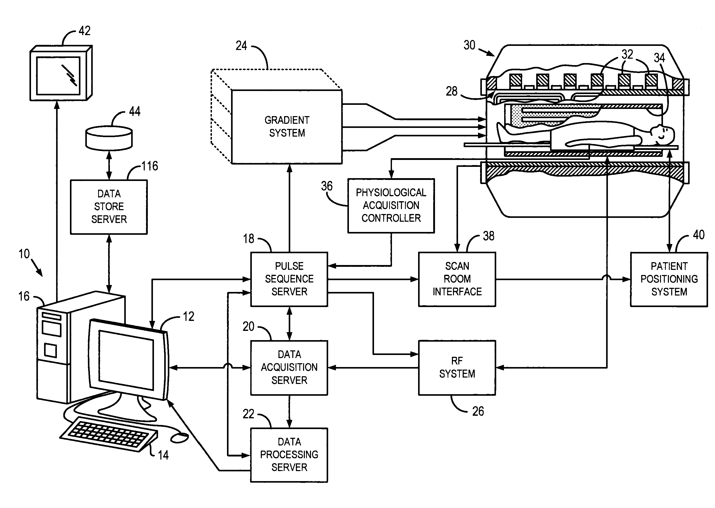
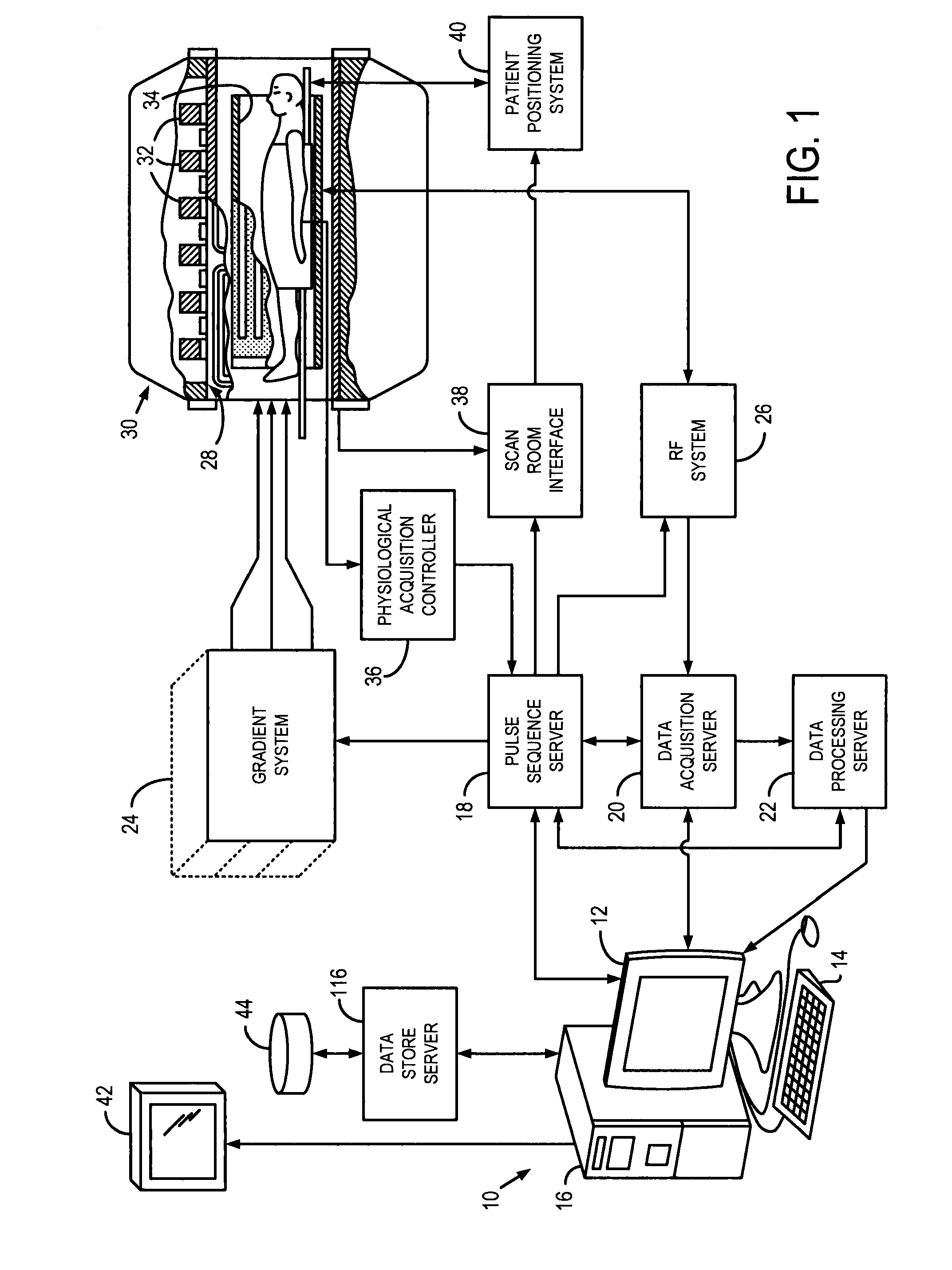
[0022]Referring particularly to FIG. 1, the invention is employed in an MRI system. The MRI system includes a workstation 10 having a display 12 and a keyboard 14. The workstation 10 includes a processor 16 that is a commercially available programmable machine running a commercially available operating system. The workstation 10 provides the operator interface that enables scan prescriptions to be entered into the MRI system.

[0023]The workstation 10 is coupled to, for example, four servers, including a pulse sequence server 18, a data acquisition server 20, a data processing server 22, and a data store server 23. In one configuration, the data store server 23 is performed by the workstation processor 16 and associated disc drive interface circuitry and the remaining three servers 18, 20, 22 are performed by separate processors mounted in a single enclosure and interconnected using a backplane bus. The pulse sequence server 18 employs a commercially available microprocessor and a com...


PUM


Abstract

A system and method is provided for magnetic resonance angiography (MRA) that includes applying a first labeling pulse sequence to a first labeling region having a first portion of a vasculature of a subject extending through the first labeling region to label spins moving within the first labeling region. A second labeling pulse sequence is applied to a second labeling region having a second portion of a vasculature of the subject extending through the second labeling region to label spins moving within the second labeling region. The first and second labeling pulse sequences include different labeling techniques. An imaging pulse sequence is applied to an imaging region having a third portion of a vasculature of the subject extending through the imaging region that is displaced from the first and second labeling region to acquire imaging data from the spins labeled by the first labeling pulse sequence and the second labeling pulse sequence. An MRA image is reconstructed of at least the third portion of the vasculature of the subject from the medical imaging data.

Description

CROSS-REFERENCE TO RELATED APPLICATIONS[0001]N / AFIELD OF THE INVENTION[0002]The invention relates to a system and method for performing magnetic resonance imaging and, more particularly, to a system and method for acquiring data suitable for arterial spin labeling (ASL).BACKGROUND OF THE INVENTION[0003]When a substance such as human tissue is subjected to a uniform magnetic field (polarizing field B0), the individual magnetic moments of the nuclear spins in the tissue attempt to align with this polarizing field, but precess about it in random order at their characteristic Larmor frequency. Usually the nuclear spins are comprised of hydrogen atoms, but other NMR active nuclei are occasionally used. A net magnetic moment Mz is produced in the direction of the polarizing field, but the randomly oriented magnetic components in the perpendicular, or transverse, plane (x-y plane) cancel one another. If, however, the substance, or tissue, is subjected to a magnetic field (excitation field ...

Claims


Application Information

Patent Timeline
IPC IPC(8): A61B5/055
CPCA61B5/02007G01R33/5635A61B5/055A61B5/0263
Inventor KOKTZOGLOU, IOANNIS
Owner NORTHSHORE UNIV HEALTHSYST
Why Eureka
Try Eureka