Optical tomographic imaging apparatus

a tomographic imaging and optical tomography technology, applied in the field of imaging methods and imaging devices for optical tomographic imaging, can solve the problems of a frame out of the imaging range, a decrease in contrast, etc., and achieve the effects of easy determination, good image quality and improved image quality

Active Publication Date: 2012-11-29
CANON KK
View PDF13 Cites 24 Cited by
  • Summary
  • Abstract
  • Description
  • Claims
  • Application Information

AI Technical Summary

Benefits of technology

[0008]According to the optical tomographic imaging apparatus of the present invention, it is possible to designate a specific area of interest in an OCT image, to designate a proper calculation index for determining the image quality of the area, and to determine whether the image quality of the area is good or not according to a calculated value obtained based on the calculation index. Therefore, it is possible to easily determine whether the obtained area of interest of a measuring person has good image quality.

Problems solved by technology

However, if an object such as a human eye is always moving, imaging conditions such as a position of focus and a position of a range of imaging change, resulting in problems such as a decrease in contrast and a frame out of the imaging range.

Method used


Image

  • Optical tomographic imaging apparatus
  • Optical tomographic imaging apparatus
  • Optical tomographic imaging apparatus

Examples


example 1

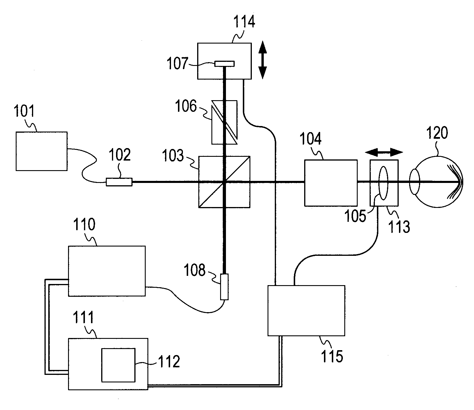
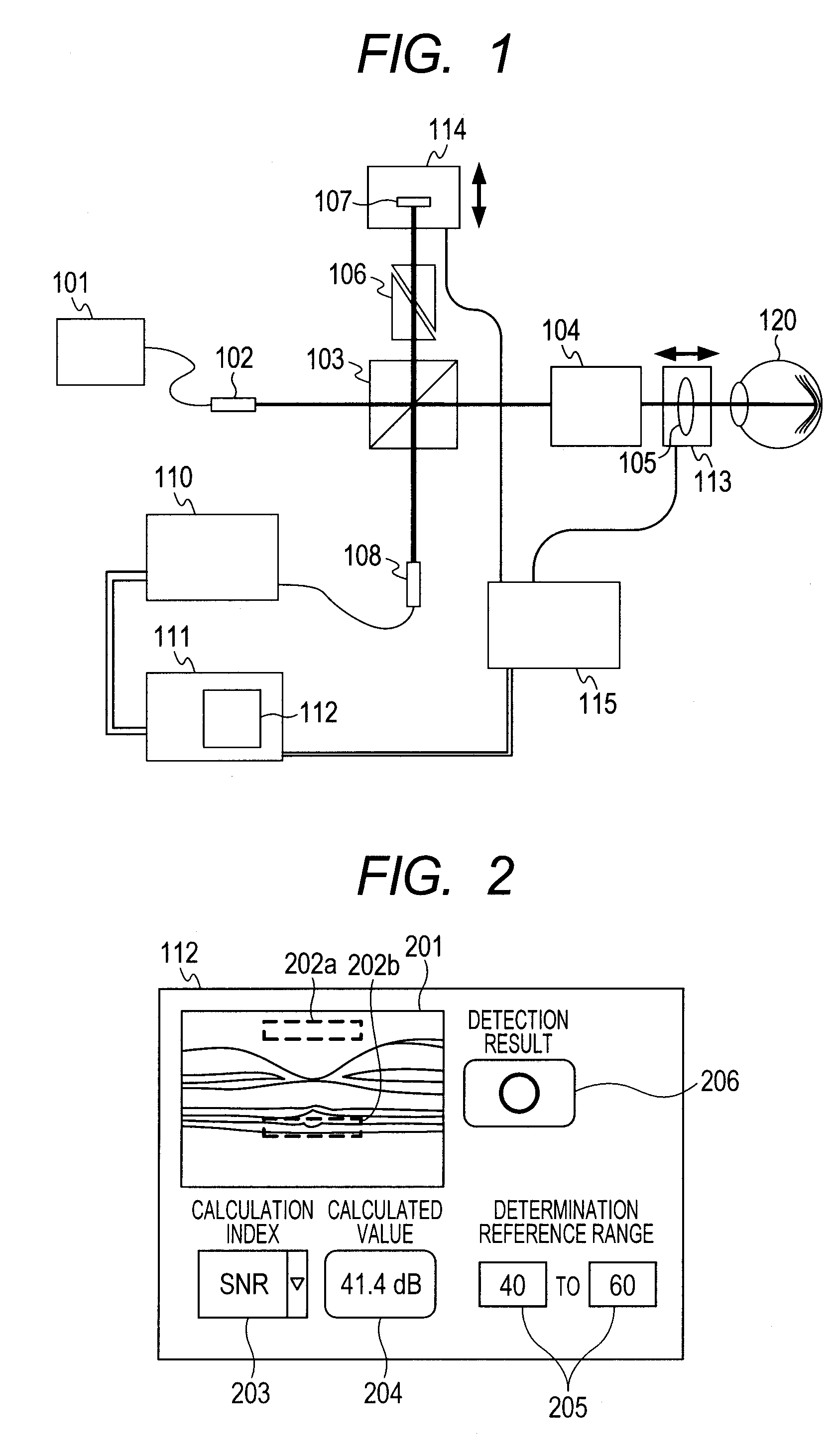
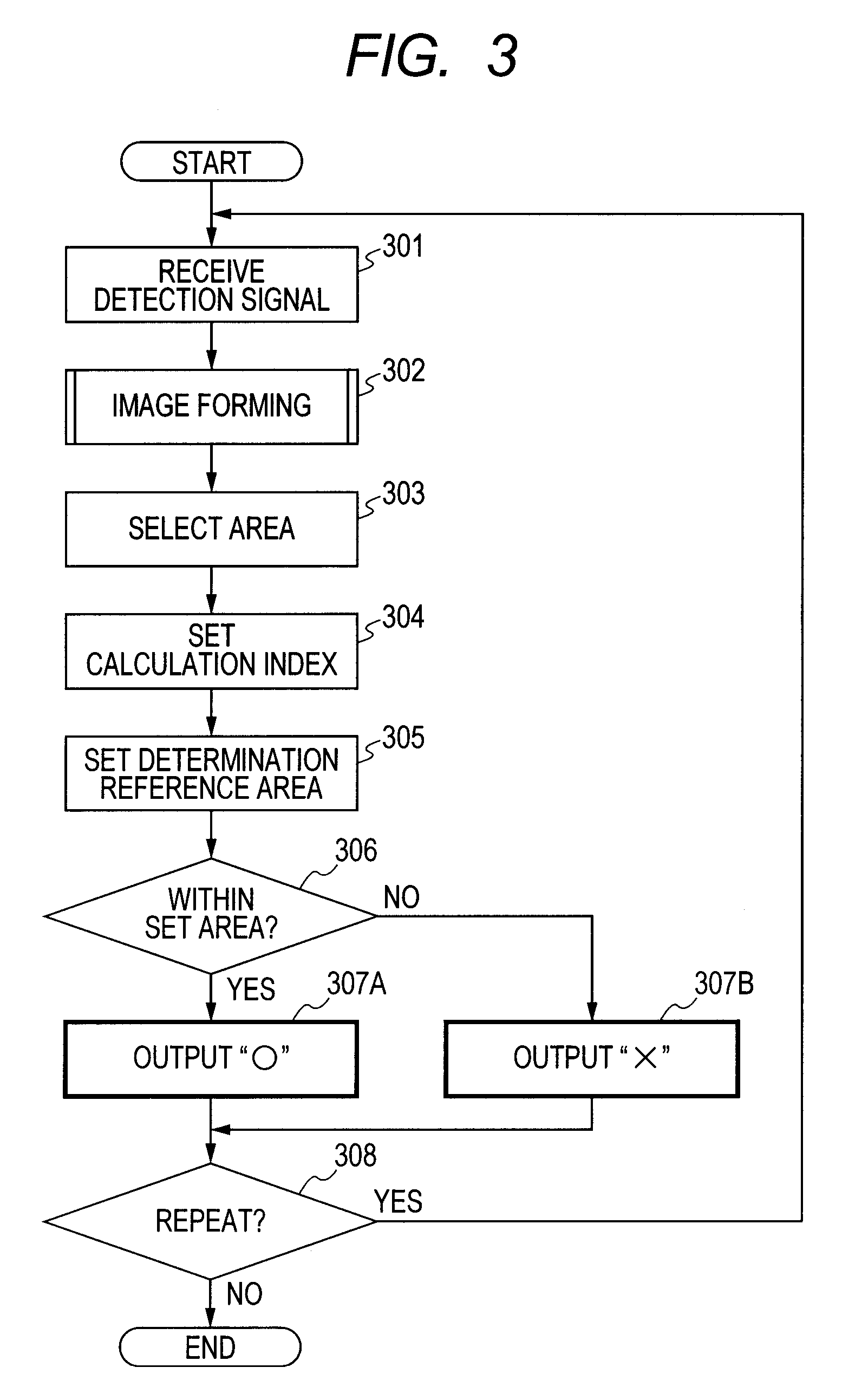
[0027]A specific example is described according to the embodiment illustrated in FIGS. 1 to 4.

[0028]A super luminescent diode (SLD) which has a center wavelength of 840 nm and a wavelength width of 45 nm is used as the low coherence light source 101. The object 120 is the human eye retina. The dispersion compensation glass 106 is made of BK7 glass, and is configured by using two dispersion prisms having a longer side of 20 mm and a shorter side of 15 mm. The longer sides are arranged so as to be parallel with the optical axis, and a standard refractive index liquid is applied to the oblique surfaces so that the oblique surfaces are adhered to each other. The thickness of the glass serving as the optical path can be changed in a range of approximately 20±10 mm by displacing the oblique surfaces.

[0029]The detection unit 110 is configured as described below. The line sensor camera has a pixel size of a 14-μm square, a pixel pitch of 14 μm, the number of pixels of 2048, and a line rate ...

example 2

[0036]This example describes a case in which the calculation index is not SNR and the area designation is different referring to FIGS. 5A to 5C.

[0037]FIG. 5A illustrates a case in which an area 501a near the neuroepithelial layer of retina directly below the central fovea is designated. According to the spectral domain OCT, the signal intensity increases as the position becomes closer to the reference mirror, and the signal intensity thus tends to increase at a neighborhood 502a of the nerve fiber layer. Thus, whether the luminance value in the area 501a is good or not can be determined by designating the area 501a, and setting the calculation index to “Maximum value”. In other words, it is possible to arbitrarily set an area of interest and to easily determine whether the luminance value is high or not.

[0038]FIG. 5B illustrates a case in which a neighborhood 501b of the internal granular layer and a neighborhood 502b of a layer next thereto are designated. In this case, it is possi...

example 3

[0044]This example describes an example of designating an area by a name of a specific portion.

[0045]Though the examples in which the designation is made by a position coordinate in the image display portion 201 are described in the preceding section, there are cases in which an area is designated more conveniently by a name of a specific portion.

[0046]FIG. 6 illustrates a case in which an area is designated by “Nerve fiber layer” (601a), and a case in which an area is designated by “Pigmented layer” (601b). When a lesion is diagnosed using OCT images, a change in a specific portion is often focused upon usually, and the specific portion can be easily designated by the name rather than the position coordinate.

[0047]Each of layers can be discriminated in advance by applying processing of calculating boundaries of each of the layers from image data (segmentation). When the object 120 is the human eye retina, options such as “Nerve fiber layer”, “External granular layer”, “Internal gra...


PUM


Abstract

Provided is an optical tomographic imaging apparatus including: a unit for creating a measuring beam and a reference beam from beam of a light source, and generating interference light by combining a return beam resulting from the measuring beam and the reference beam; a unit for detecting the interference light to generate a detection signal; a unit for forming an image of the object based on the detection signal; a unit for designating a specific area in the image; a unit for setting a calculation index and a determination reference range used for determining image quality of the specific area; and a unit for applying calculation processing to a luminance value of the specific area based on the calculation index, determining whether a calculated value obtained as a result of the calculation processing is within the determination reference range, and outputting a detection result.

Description

TECHNICAL FIELD[0001]The present invention relates to an imaging method and an imaging device for optical tomographic imaging, and more particularly, to an imaging method and an imaging device for optical tomographic imaging employing an optical coherence tomography used in, for example, ophthalmologic diagnosis and treatment.BACKGROUND ART[0002]In recent years, an optical coherence tomographic imaging method and an optical coherence tomographic imaging apparatus, to which a low coherence interferometer technology or a white light interferometer technology is applied, are in actual use. In particular, an optical tomographic imaging apparatus (optical interferometer apparatus) that performs optical coherence tomography (OCT) utilizing interference phenomenon of multi-wavelength light may obtain a tomogram of a sample with high resolution. Therefore, in the ophthalmological field, the optical tomographic imaging apparatus is becoming an indispensable apparatus for obtaining a tomogram...

Claims


Application Information

Patent Timeline
Patent Type & Authority Applications(United States)
IPC IPC(8): G01B9/02
CPCA61B3/102A61B5/0066G06T7/0002G06T2207/30168G06T2207/20104G06T2207/30041G06T2207/10101A61B3/10G01B9/02G01N21/17G06T7/00G01B9/02091G01B2290/70G06T7/0014
Inventor YUASA, TAKASHI
Owner CANON KK
Why Eureka
Try Eureka