[0011]
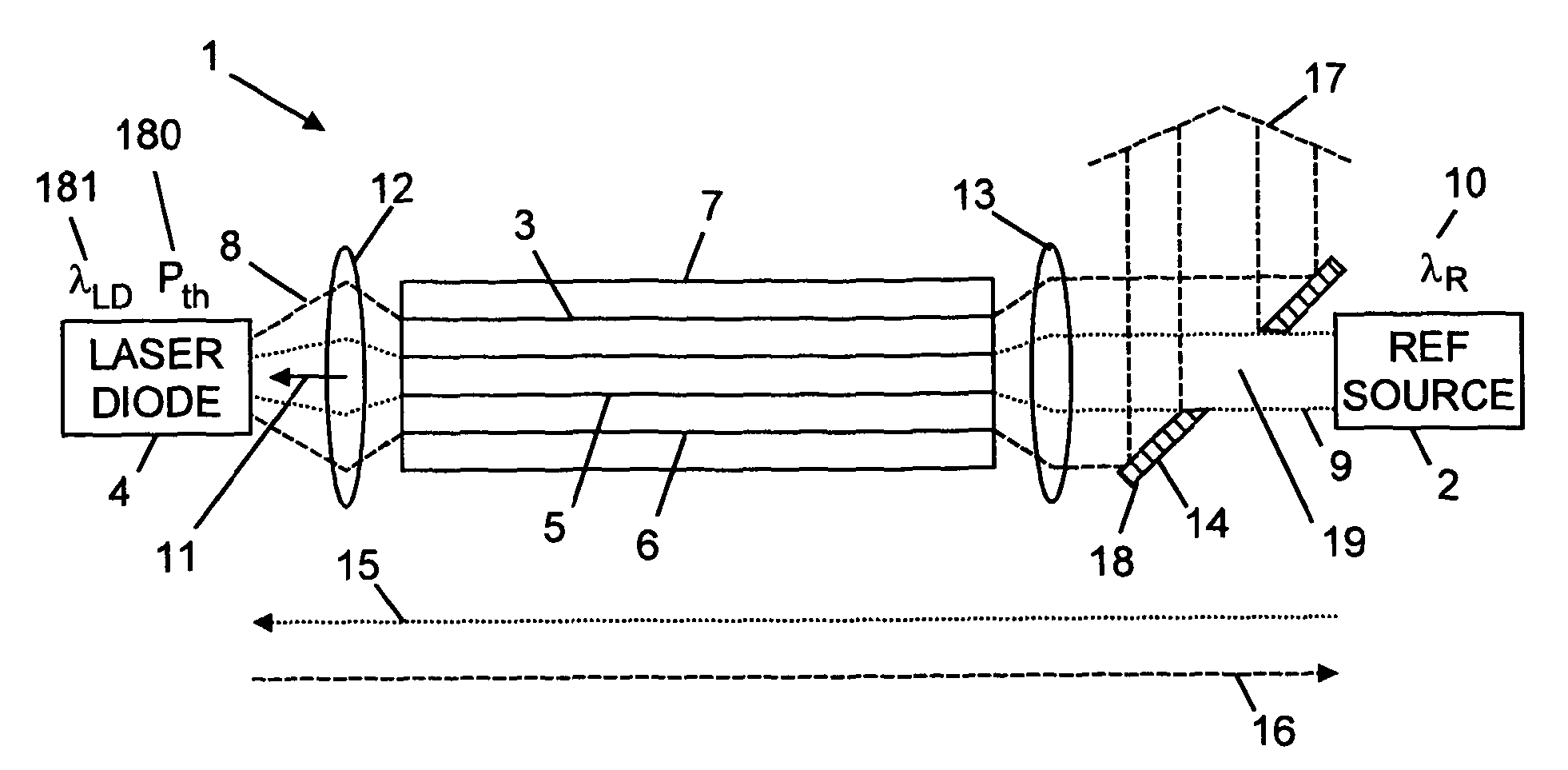
Injection locking is a process whereby the output frequency of a first oscillator is controlled by
coupling radiation from a second, usually more stable oscillator into the first oscillator. In general, laser diodes have poorly defined wavelengths, that are temperature dependent, and which vary as the laser diode is switched on. By
coupling the reference radiation from the reference source into the laser diode, it is possible to injection lock the laser diode such that its output wavelength is forced to become substantially equal to the wavelength of the reference radiation. This enables the wavelength of the laser diode to be determined by selecting a reference source that emits at the predetermined wavelength. It also enables the wavelength of the laser diode to be stabilized as it establishes
thermal equilibrium shortly after it is turned on.
[0013]Advantageously, the invention provides a means to injection lock the laser diode, and in particular a multimode laser diode, rapidly, and simply, and to do this while providing high levels of output powers (greater than 60% of the power emitted by the laser diode, preferably greater than approximately 90%, and more preferably greater than 95%) at a laser output with a wide selection of
injection locked wavelengths that are defined by the choice of the predetermined wavelength of the reference source. Suitable predetermined wavelengths include: the peak absorption wavelength of a rare-earth doped fibre laser, rod laser, or
disk laser; a wavelength at which heat dissipation is reduced or preferably minimized in a fibre laser, rod laser, or
disk laser; and a wavelength which optimizes efficiency within a fibre laser, rod laser, or
disk laser. These features are consistent with achieving a fast modulation rate of wavelength-locked pump radiation in fibre lasers, rod lasers and disk lasers, which is necessary for rapid
process control in marking,
cutting,
welding and
brazing applications. Moreover, it allows such fast modulation rates to be achieved with increased efficiencies, reduced
amplifier fibre lengths, which combination leads to lower non-linear effects (such as
self phase modulation) and / or higher peak powers being available from amplifiers and lasers. The invention solves the problem of poor wavelength control and
repeatability of multimode laser pump diodes, namely poor wavelength
repeatability from
device to device±10 nm, strong temperature dependent wavelength (0.3 nm / K), and strong power-dependence on wavelength (1 nm / W). The invention permits amplified optical signals to have high beam quality and
high peak powers for optimum
materials processing capability without necessitating the high optical intensities within the core during the amplification of high-power
optical radiation. It permits shorter fibre lengths to be used to avoid undesirable optical non-linearities. It is particularly useful for reducing
pulse distortion owing to
self phase modulation and stimulated
Brillouin scattering in pulsed fibre lasers having average powers of 10 W to 50 W and peak powers in excess of 5 kW. It is also useful for reducing non-linear effects such as
stimulated Raman scattering in high-power single moded or few moded (beam quality M2 in the range 2 to approximately 20) continuous-wave lasers having power levels in excess of 100 W, 400 W, 1 kW or more preferably, in excess of 4 kW.
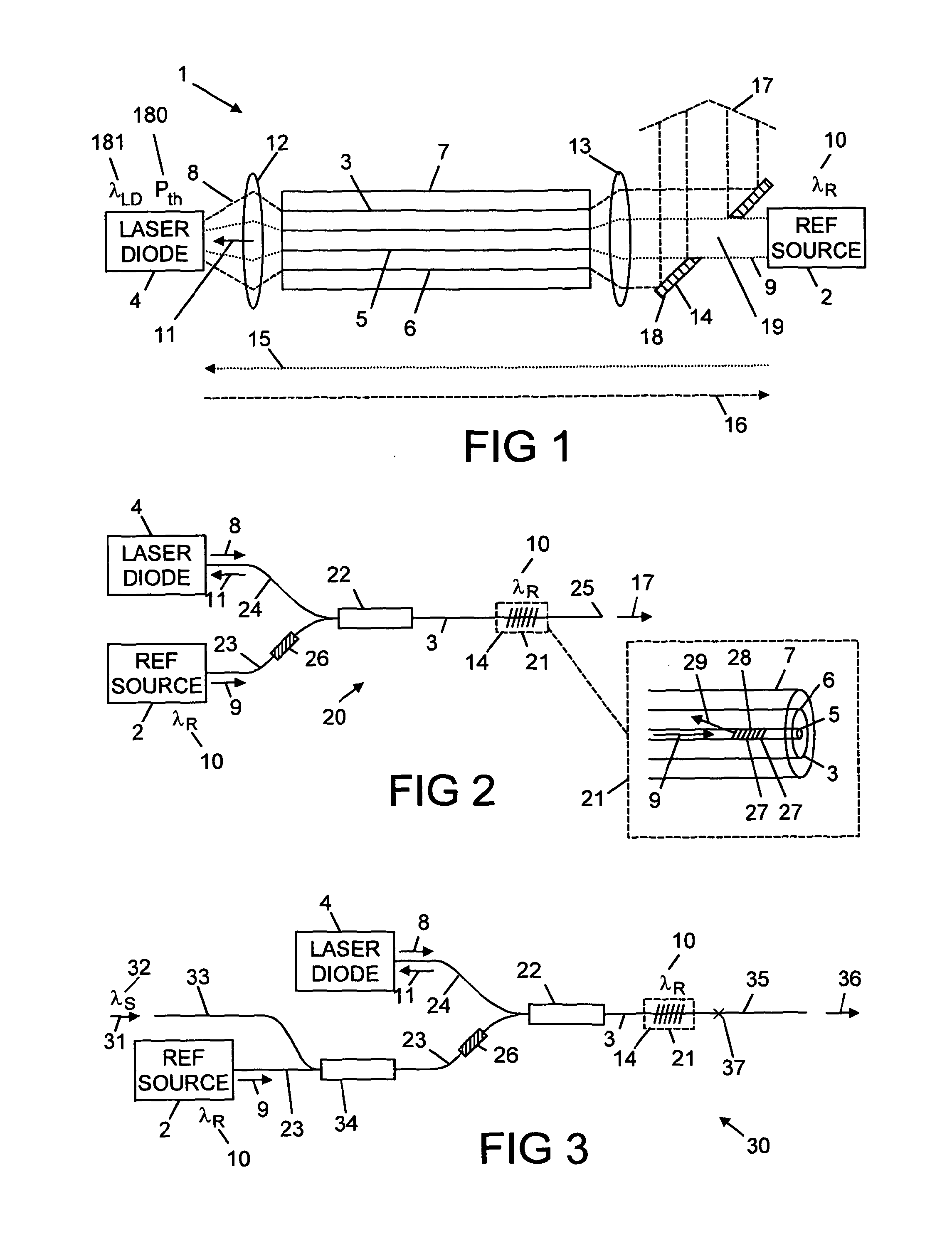
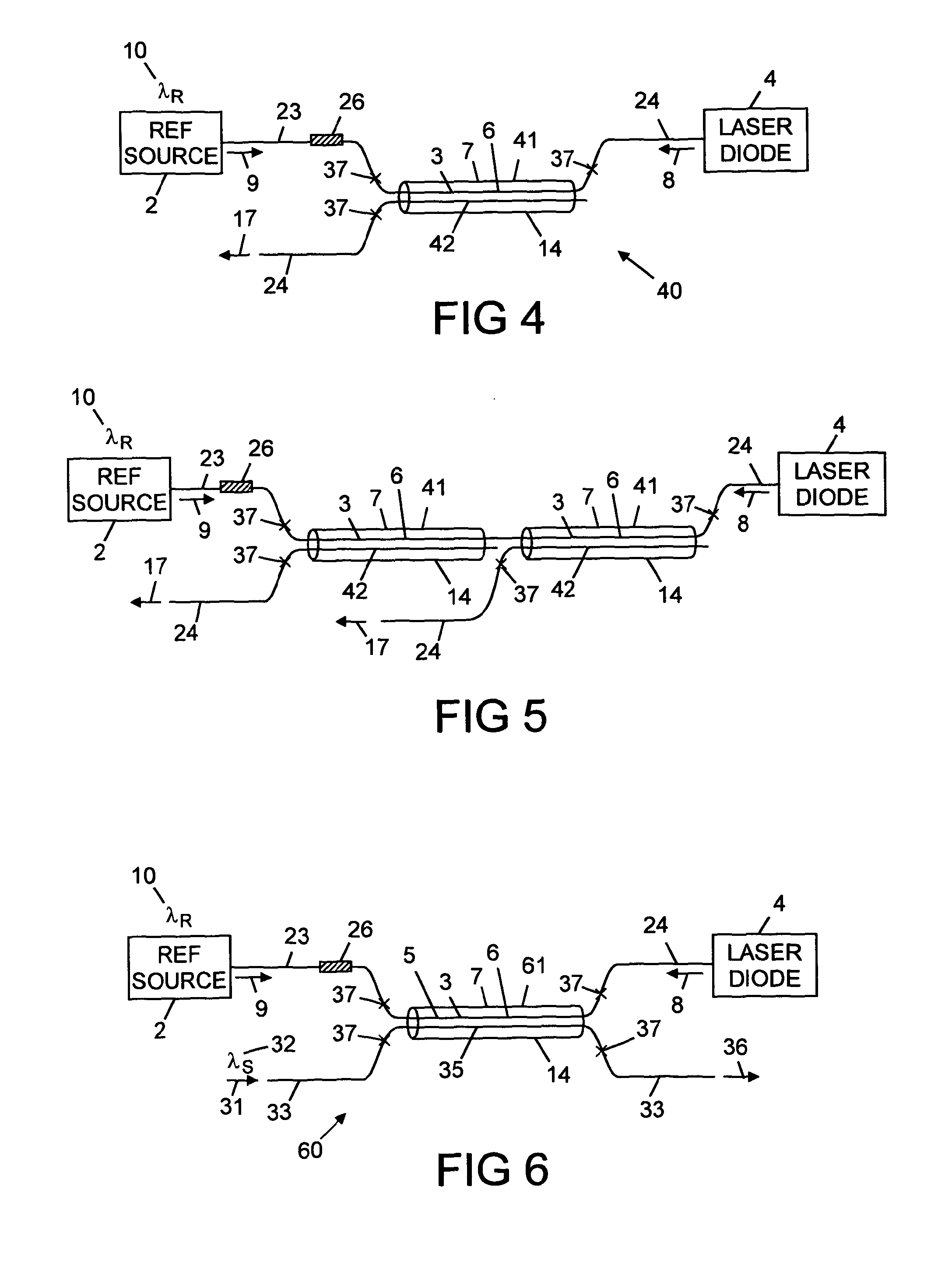
[0015]The reference source may be such that the product of its power at the predetermined wavelength and a first loss experienced by the reference radiation in propagating from the reference source to the laser diode is at least 0.5% of the power of the laser radiation emitted by the laser diode. This is to ensure that there is sufficient of the reference radiation incident on the laser diode to injection lock it reliably and repeatedly. Preferably the laser apparatus is designed to minimize the first loss in order to maximise the reference radiation received by the laser diode.
[0016]The laser apparatus may be one in which a second loss experienced by the laser radiation in propagating from the laser diode to the reference source is such that the product of the second loss and the power emitted by the laser diode is less than 10% of the power emitted by the reference source. This is to ensure that the laser radiation does not damage the reference source. Preferably the laser apparatus is designed to increase or maximise the second loss in order to minimize the laser radiation received by the reference source.

