
Method And Apparatus Of Switched Amplification Having Improved Efficiency

a technology of switching amplifier and efficiency, which is applied in the direction of amplifiers, amplifiers with semiconductor devices/discharge tubes, digital transmission, etc., can solve the problem of limiting the suitability of class s amplifers to coding efficiency, and achieve the effect of reducing power efficiency in amplifiers, reducing power loss in output bandpass filters, and increasing switching rates

Active Publication Date: 2012-11-29
ALCATEL LUCENT SAS
View PDF5 Cites 6 Cited by
  • Summary
  • Abstract
  • Description
  • Claims
  • Application Information

AI Technical Summary

Benefits of technology

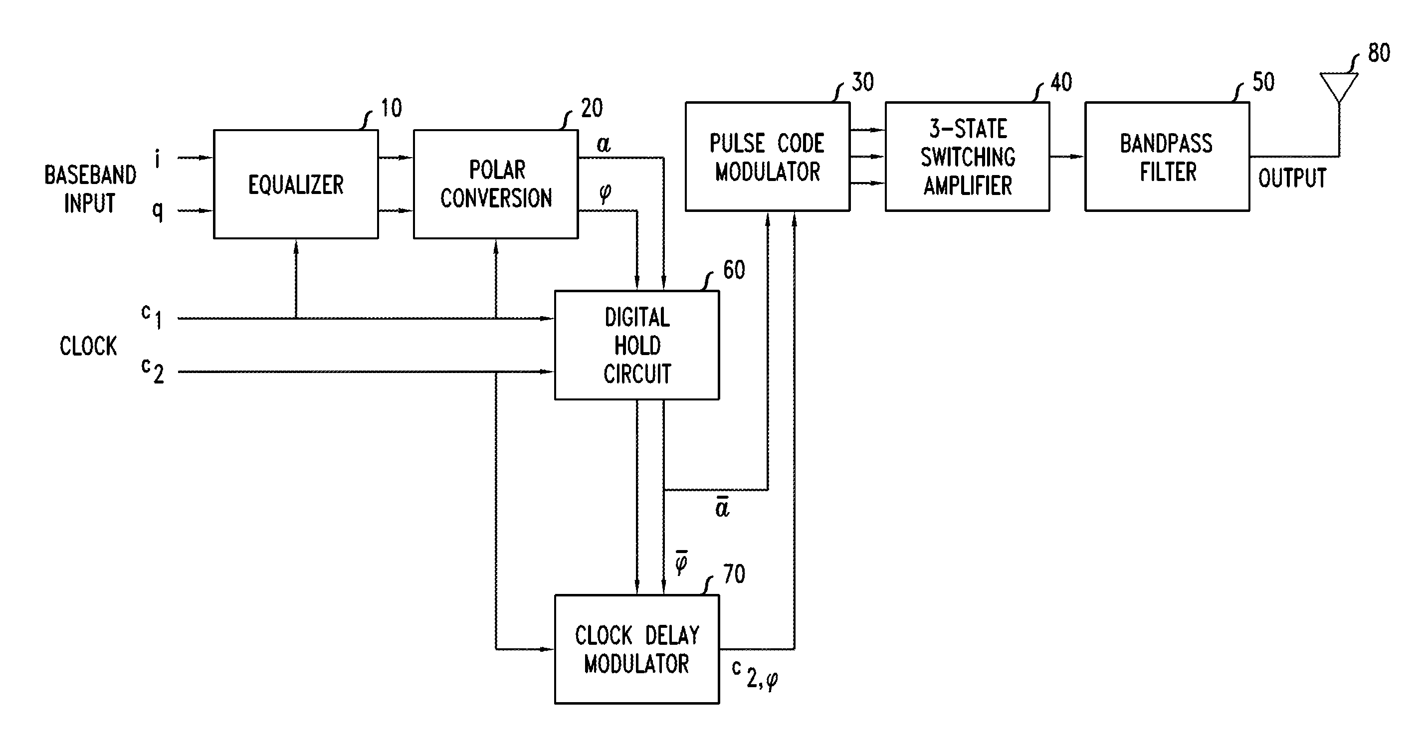
[0005]We have developed a new signal coding technique for switching amplifiers, such as Class S amplifiers, that offers the possibility of significantly improved coding efficiency.
[0020]The more efficient a code is, the more it concentrates signal power in the desired frequency band, i.e., the band to be used for transmission. Accordingly, the use of an efficient code reduces power loss in the output bandpass filter. The codes described here are designed to be relatively efficient. The concentration of power at the carrier frequency is readily seen, for example, in FIGS. 7, 8, and 9b, which are discussed below.
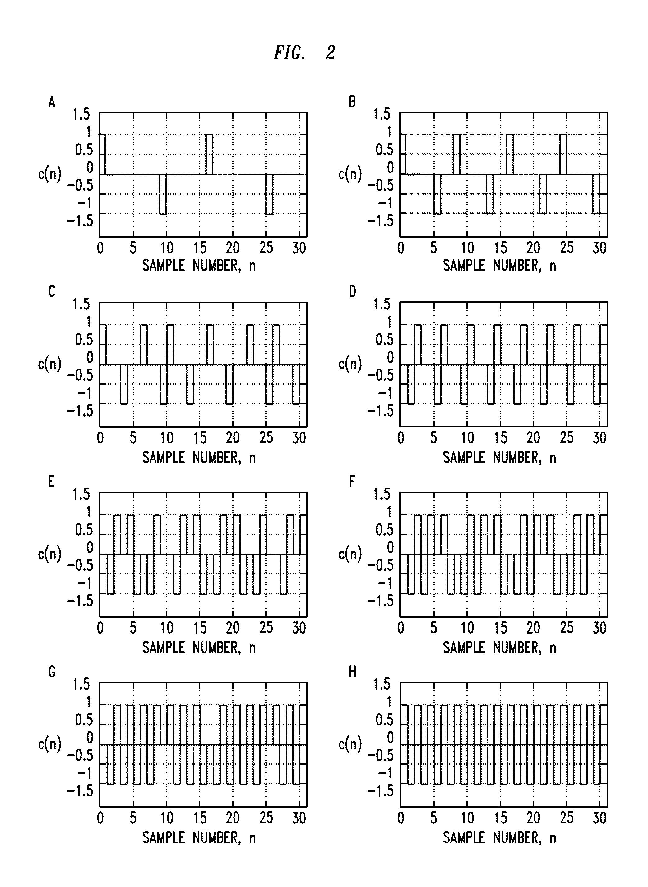
[0021]Switching loss is another mechanism that reduces power efficiency in the amplifier. Switching loss is the result of transient radiation and other transient dissipative processes that occur when the amplifier switches between ON and OFF, or between different signal levels. As a consequence, increasing the switching rate tends to increase the switching loss. By basing our codes on half-cycle pulses at the carrier frequency, with modulation by skipping some of the half-cycle pulses, we have been able to minimize the switching rate and thus we expect the codes to achieve relatively low switching loss.
[0022]The high code efficiency and low switching loss exhibited by our codes complement each other and lead to relatively high overall power efficiency.

Problems solved by technology

One factor that may limit the suitability of Class S amplifers is the coding efficiency.

Method used


Image

  • Method And Apparatus Of Switched Amplification Having Improved Efficiency
  • Method And Apparatus Of Switched Amplification Having Improved Efficiency
  • Method And Apparatus Of Switched Amplification Having Improved Efficiency

Examples


example 1

[0076]We performed a numerical simulation of the response of our model system, with a damping factor of 0.005, to a sequence of positive and negative pulses having T=5 and τ=0.5. We took 100 samples per cycle, extended the computation to 200 cycles, and took the last 100 cycles as representative of steady-state behavior. We performed a spectral analysis of the resulting 10,000-sample segment using a Hamming window. The result is shown in FIG. 7a. For a better understanding of the figure, it should be noted that for computational convenience, and without loss of generality, we normalized the center frequency to 1 Hz. As seen in the figure, the center frequency occurs at a normalized frequency of 0.02, which reflects a further normalization factor due to our sampling at 100 samples per cycle and considering the Nyquist rate of two samples per cycle.

[0077]A sequence of spurious tones, which we refer to as spectral “spurs”, are seen in the figure, at frequencies (relative to a center fr...

example 2

[0080]FIGS. 8a and 8b show output spectra for simulations of the response of our model system to pulse codes, as described here, in which a=⅓ and M equals 8 and 32, respectively. The computation was similar to that of Example 1. Comparison of the two spectra shows that when the number of amplitude quantization levels is reduced, additional spurs appear (due to intermodulation) between the main spurs that are associated with pulse skipping. From these results, we expect that intermodulation will not present intolerable difficulties at least when M is at least 8.

example 3

[0081]FIGS. 9a and 9b provide a simple example of pulse-code amplitude modulation combined with phase modulation. Our simulation was modified to include phase modulation according to the clock-delay technique described above, but was otherwise similar to the preceding two examples. We computed the response of our model system to a two-tone suppressed carrier signal x(t), coded with M=16.

[0082]The input signal is given by x(t)=α cos(ω0+Δ)t+(1−α)sin(ω0−Δ)t, where 0≦α≦1 controls the ratio of tone amplitudes and Δ is the tone spacing above and below the center frequency ω0. The amplitude a(t) and phase φ(t) of the input signal are respectively given by

a(t)=[1-2α+2α2+2α(1-α)cos2Δt]1 / 2ϕ(t)=tan-1[(2α-1)sinΔtcosΔt]

[0083]The upper view in FIG. 9a is the waveform for the coded input signal for α=⅓, and the lower view is the corresponding output waveform. It will be seen that the output amplitude varies as a quasi-sinusoid between limits of 0.33 and 1 as expected from the above equations. FIG....


PUM


Abstract

A signal coding technique for switching amplifiers includes quantizing the amplitude A(t) of an input signal to produce a time series Â(t) having M levels; modulating a clock signal in response to Â(t), thereby to produce a control signal; switching among at least three different power supply output levels in response to the control signal, thereby to generate an output pulse stream; and filtering the output pulse stream to produce an output signal for transmission.

Description

FIELD OF THE INVENTION [0001]The invention relates to electronic amplification of radiofrequency signals, and more particularly to switching amplifiers for power amplification in communication systems.ART BACKGROUND [0002]The power amplifier is typically the last stage in the processing of signals for transmission from a wireless base station. Power efficiency is a critical performance metric for these and similar amplifiers. In a base station, for example, the power amplifiers may account for as much as half the total power expenditure. Both to reduce operating costs and to mitigate thermal loads, there is a need to improve the efficiency of power amplifiers.[0003]Several well-known techniques have been applied to improve power efficiency, including the use of Doherty amplifier designs, envelope elimination and restoration, and linear amplification with nonlinear components. Another possible approach is to use Class S switching amplifiers for power amplification. Such amplifiers ar...

Claims


Application Information

Patent Timeline
IPC IPC(8): H04B14/04H04L27/00
CPCH04B14/04H03F3/217
Inventor MORGAN, DENNIS R.
Owner ALCATEL LUCENT SAS
Learn More