Ultra high pressure turbomachine for waste heat recovery

a high-pressure turbomachine and waste heat recovery technology, which is applied in the direction of electric generator control, magnetic circuit rotating parts, magnetic circuit shape/form/construction, etc., can solve the problems of oil contamination of process gas, unreliable oil-lubricated bearings used in the device of u.s. pat. no. 5,045,711, and other problems, to achieve the effect of preventing process gas leakage, minimizing the windage of the alternator shaft, and minimizing iron

Active Publication Date: 2012-12-06
R & D DYNAMICS
View PDF7 Cites 55 Cited by
  • Summary
  • Abstract
  • Description
  • Claims
  • Application Information

AI Technical Summary

Benefits of technology

[0014]In preferred embodiments, the turbine side of the turbomachine comprises a centrifugal-type shrouded impeller with straight-through labyrinth seals on the front and the rear, a turbine collector with an inlet and an outlet for the process gas, a turbine nozzle, turbine bearing housings, and a turbine shaft supported on hydrodynamic journal bearings and thrust foil gas bearings. Further, the turbine housing includes a bell housing encasing the coupling shaft and two-stage labyrinth seals to prevent process gas leakage into an alternator side of the turbomachine.
[0018]Further, the alternator stator is preferably made of laminated sheets of thin electrical steel with copper windings in stator slots. The thin steel minimizes losses in the iron of the stator. The stator is cooled by liquid through a jacket around the alternator housing.
[0019]In another aspect of the present invention, a low-pressure adapter housing is connected between static portions of the turbine and of the alternator. Respective rotating portions of the turbine and the alternator are connected by a coupling shaft extending through the adapter housing. This coupling shaft transmits torque from the turbine to the alternator during power take out from the alternator leads. The coupling shaft preferably comprises an adapter end which slides onto the turbine shaft and a splined end that slides into the female coupler end of the alternator shaft. The coupling shaft has stages of labyrinth seals to prevent process gas leakage into the atmosphere. In order to minimize alternator shaft windage due to high pressure and the speed, the alternator side is isolated from the turbine via the coupling shaft. Windage on the alternator shaft is due to shearing of the highly viscous fluid in the stator-rotor cavity gap. Therefore, the turbine side preferably runs with a high-pressure process gas whereas alternator side runs with an ambient air.
[0022]In further accordance with the present invention, the alternator side makes use of a unique self-sustained internal cooling flow circuit. The cooling fan is preferably a centrifugal-type impeller with a collector for air inlet and outlet. The impeller is directly coupled to the alternator rotor assembly and shaft. Compressed air from the cooling fan impeller provides cooling for the journal and thrust bearings in the alternator side. The same cooling flow is used to dissipate heat in the alternator housing due to windage between the rotor and the stator. Specifically, cooling channels allow airflow below the magnets. Liquid cooling is also used to dissipate heat from the stator. As a result, the alternator design of the present invention does not require any external cooling source to keep the machine cool.

Problems solved by technology

Unfortunately, oil-lubricated bearings as used in the device of U.S. Pat. No. 5,045,711 are unreliable, especially at the high running speeds more typical of and expected from modern turbomachinery devices.
Further, shaft seals tend to wear out quickly and oil contamination of the process gas becomes a significant problem.
Unfortunately, titling pad bearings still suffer from high power loss, mechanical complexity, pivot fretting, limited damping capacity and indirect measurement of bearing loading.
Heretofore, known problems with turboalternator devices arose due to the excessive size and complexity of such devices.

Method used


Image

  • Ultra high pressure turbomachine for waste heat recovery
  • Ultra high pressure turbomachine for waste heat recovery
  • Ultra high pressure turbomachine for waste heat recovery

Examples


Embodiment Construction

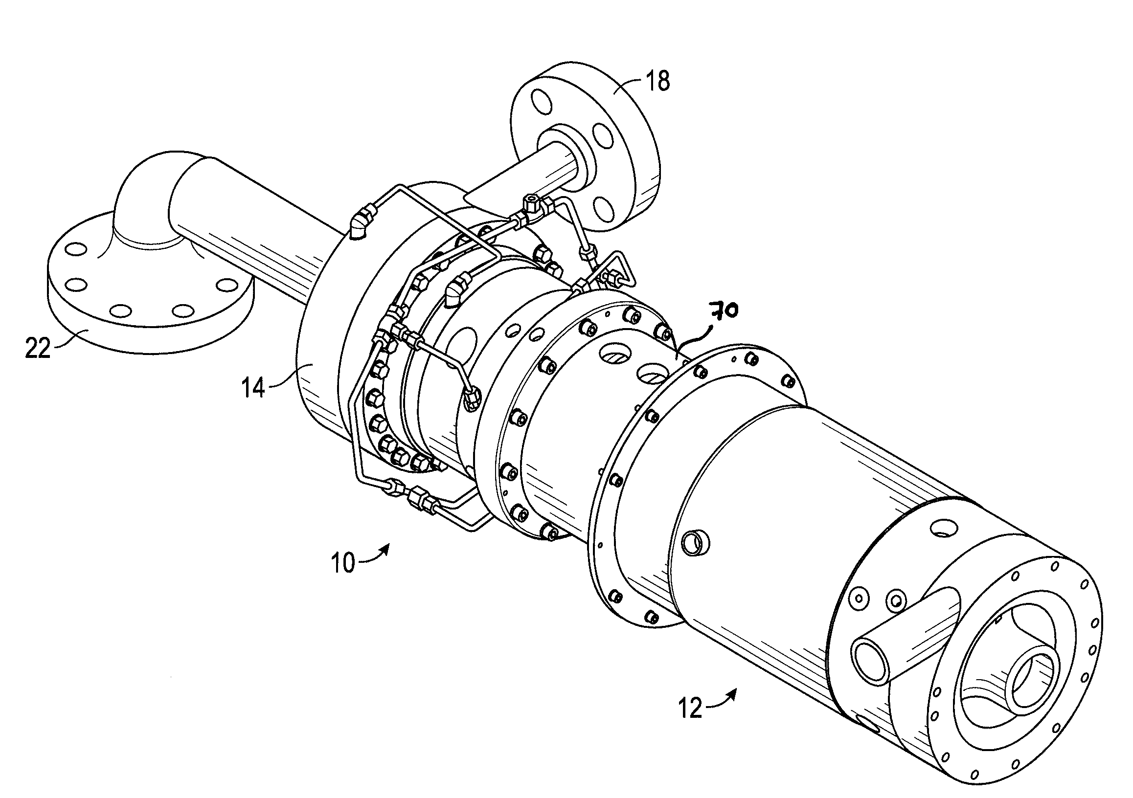
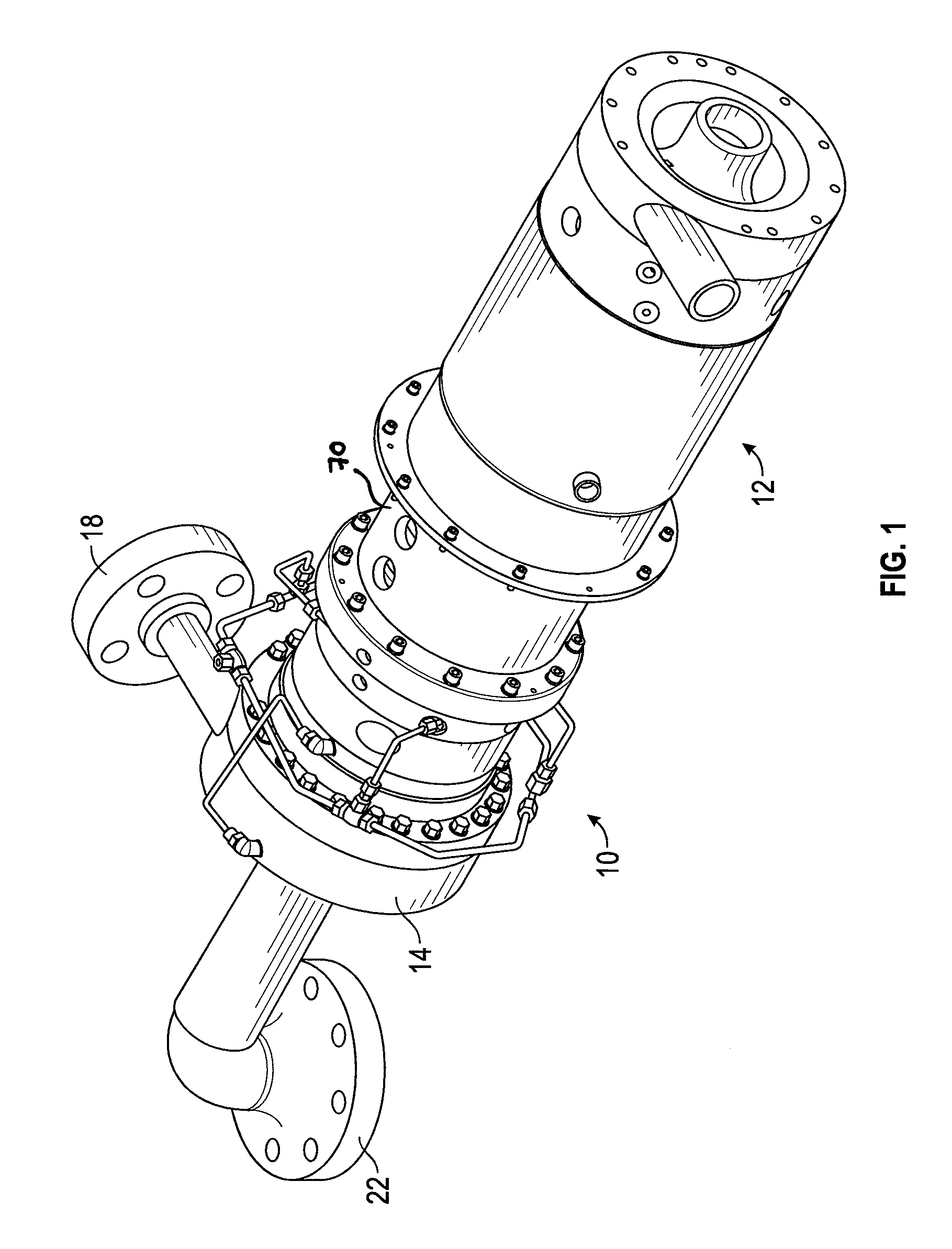
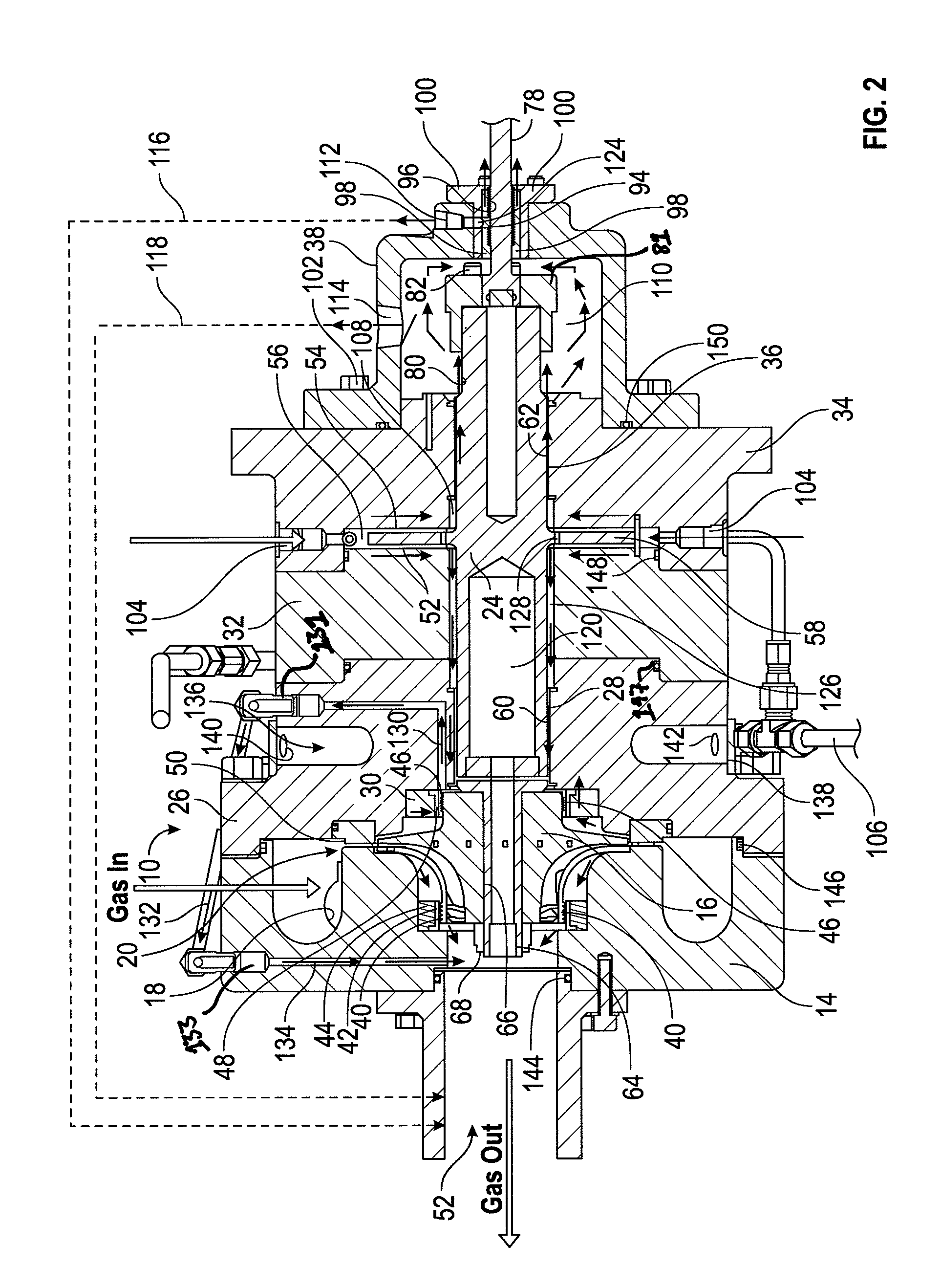
[0034]The present invention is directed to a power generating system for recovering energy stored in a process gas. A perspective view and cross-sectional view of an exemplary turbine-driven alternator in accordance with the present invention are illustrated in FIGS. 1 and 2, respectively. The illustrated turbine-driven alternator (hereinafter “turboalternator”) is preferably a small, high efficiency, oil-free device that can be used in various applications, such as for compressed air energy storage, waste gas energy recovery, pressure letdown, gas liquefaction, and low temperature Organic Rankine Cycles.

[0035]The Organic Rankine Cycle's principle is based on a turboalternator working as a steam turbine to transform thermal energy into mechanical energy and finally into electric energy through an electric generator. Instead of water steam, the ORC system vaporizes an organic fluid, characterized by a molecular mass higher than water, which leads to a rotation of the turbine and prod...


PUM


Abstract

A turbine-driven alternator (i.e., a turbomachine) suitable for generating electrical power from process gas waste energy. In particular suitable for very high density process gases such as super critical CO2, R134a, R245fa, etc. The turboalternator comprises two separate machines, specifically, a turbine device and an alternator device operatively connected together by a coupling shaft. The rotating shaft assemblies for each machines on the turbine side and the alternator side are supported by hydrodynamic foil gas bearings. The foil gas bearings use process gas at the turbine side, enabling high-pressure operation (˜3000 psia) and thrust load balancing. At the alternator side, cooling fluid is used in the foil gas bearings, enabling high-speed (˜40,000 rpm), low-windage, oil-free operation with closed-loop shaft cooling.

Description

CROSS-REFERENCE TO RELATED APPLICATIONS[0001]This application claims the benefit under 35 USC §119(e) of U.S. Provisional Application No. 61 / 492,233, filed Jun. 1, 2011, and under 35 USC §119(a) of U.S. application Ser. No. 13 / 191,979, filed Jul. 27, 2011. Those priority applications are incorporated herein by reference.FIELD OF THE INVENTION[0002]The present invention relates generally to turbomachinery, and more particularly to turbine-driven alternators used to convert energy stored in a process gas into electrical energy.BACKGROUND OF THE INVENTION[0003]Turbine-driven alternators, namely turboalternators, are a key piece of machinery in many different systems for generation of energy. In a turboalternator, a turbine converts stored energy in a process gas to mechanical energy. An alternator, which is typically coupled to the turbine via a coupling shaft, converts the mechanical energy into electrical energy. The electrical energy is then supplied to a load. Such a turboalternato...

Claims


Application Information

Patent Timeline
Patent Type & Authority Applications(United States)
IPC IPC(8): H02K7/18
CPCF04D25/0606F04D25/024F01D15/10F01D25/125F01D25/168F04D29/0513H02K1/32
Inventor AGRAWAL, GIRIDHARI L.BUCKLEY, CHARLES W.SHAKIL, ALICOWARD, ANDREW HAMILTON
Owner R & D DYNAMICS
Why Eureka
Try Eureka