
Light source apparatus

a technology of light source and light source, which is applied in the field of light source apparatus, can solve the problems of reducing the illumination of white light at the distal side, and achieve the effect of sufficient biological surface illumination, avoiding false negative and false positive judgments, and being effective to the feeling of users

Inactive Publication Date: 2012-12-06
FUJIFILM CORP
View PDF1 Cites 19 Cited by
  • Summary
  • Abstract
  • Description
  • Claims
  • Application Information

AI Technical Summary

Benefits of technology

[0029]According to the light source apparatus of the present invention, exit angles of first and second light guided by the light guide section and projected onto an examination area are changed simultaneously. This allows the ratio between the projection range of the first light and projection range of the second light to be set to a desired predetermined value without requiring complicated operations, while maintaining sufficient biological surface illuminance for both the first and second light.
[0030]Thus, in the case where the first light is near infrared excitation light and the second light is visible light, the ratio between the projection range of the excitation light and the projection range of the visible light may be maintained constant, and the user may know the ratio, so that the user may know to which portion the excitation light is projected with respect to the projection range of the visible light. Consequently, false-negative and false positive judgments may be avoided.
[0031]Further, in the case where the upstream optical system for receiving either one of the first and second light and inputting the received either one of the light to the incident angle changing optical system is further provided, and incident height of the either one of the light to be inputted to the incident angle changing optical system by the upstream optical system is changed along with the change in the exit angles by the incident angle changing optical system, another advantageous effect may be obtained. That is, it is more effective to the feeling of the user to maintain the ratio between exit angles of the first and second light constant rather than maintaining the ratio between the radii of projection ranges thereof constant.

Problems solved by technology

In such a case, use of the endoscope system described in U.S. Patent Application Publication No. 20020026099 may cause a problem that the illuminance of white light at the distal side may be reduced as the exit angle of the white light is fixed, although the illuminance of the excitation light may be maintained at a sufficient level at the distal site by narrowing the exit angle thereof.
Further, even if the exit angle of the white light is made changeable in the endoscope system described in U.S. Patent Application Publication No. 20020026099, a problem that an image with an inappropriate ratio between the projection range (radius) of excitation light and projection range (radius) of white light is captured or otherwise a complicated procedure for adjusting the ratio is required if there is not any consistent relationship between the change in exit angle of the excitation light and change in exit angle of the white light.

Method used


Image

  • Light source apparatus
  • Light source apparatus
  • Light source apparatus

Examples


first embodiment

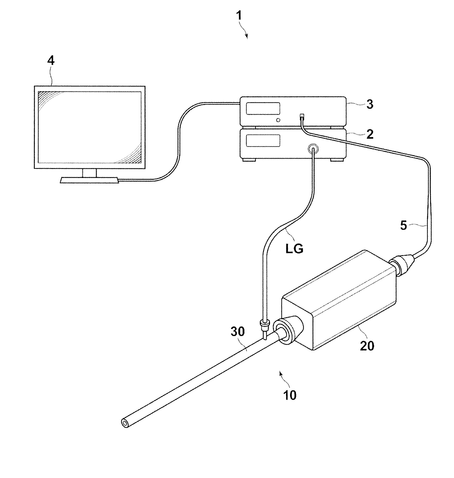
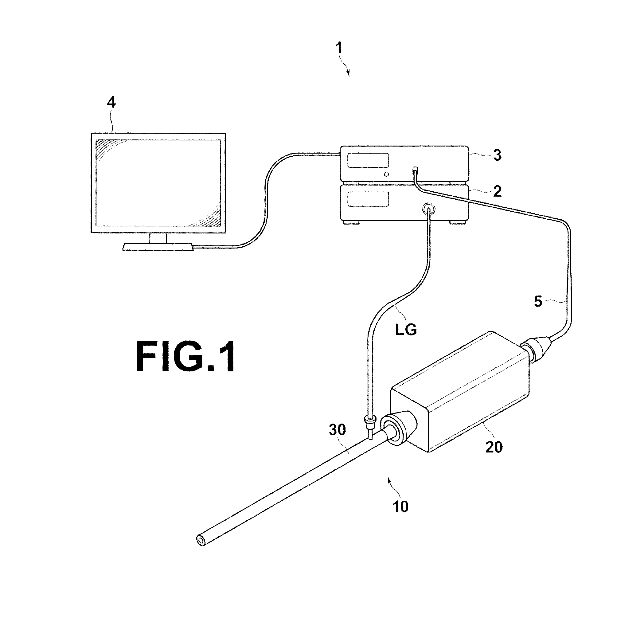
[0053]Hereinafter, a rigid endoscope system that employs the light source apparatus of the present invention will be described in detail with reference to the accompanying drawings. The rigid endoscope system of the present embodiment has a characteristic feature in the configuration of the light source apparatus, but an overall system configuration will be described first. FIG. 1 is an overview of the rigid endoscope system 1, illustrating a schematic configuration thereof.

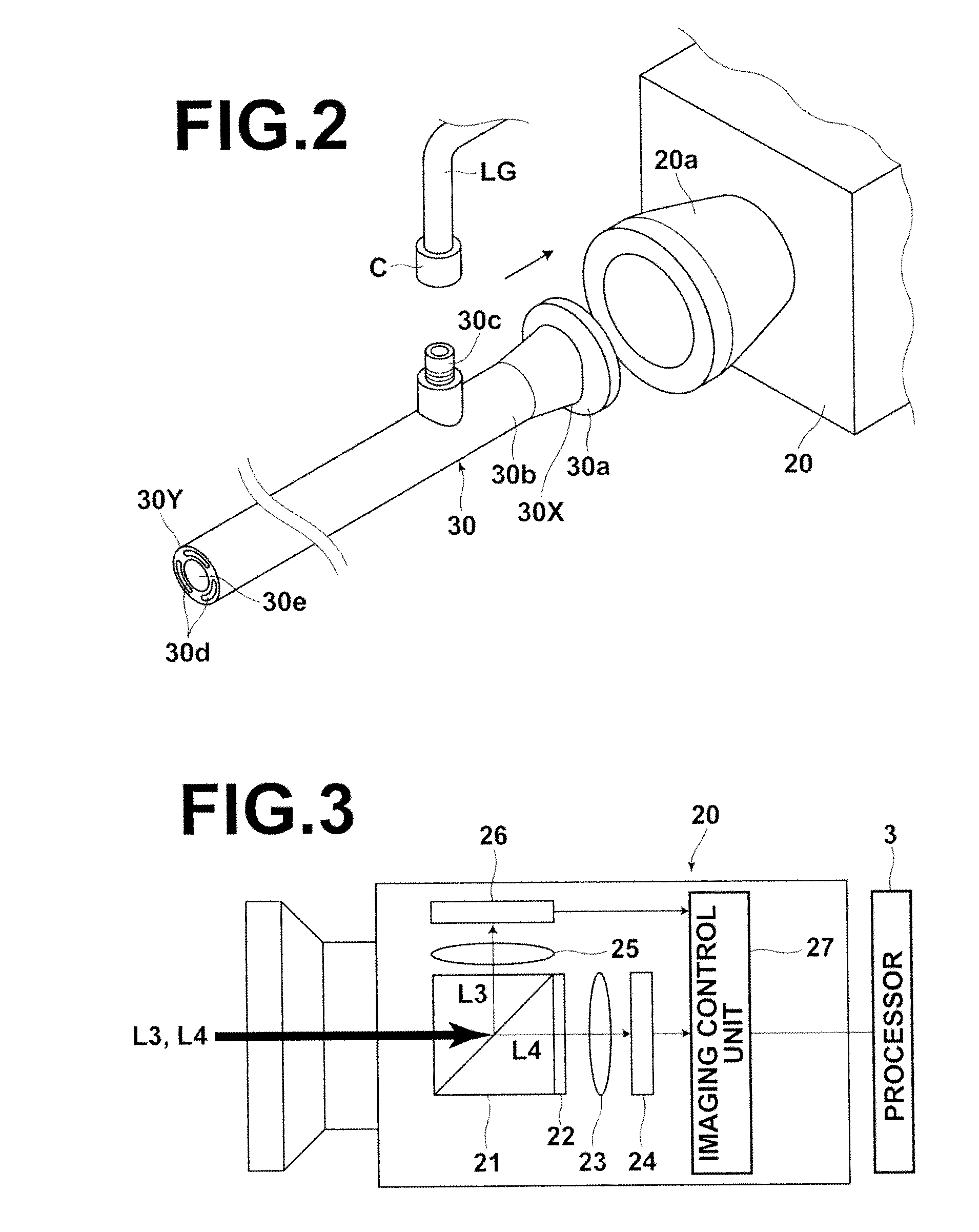
[0054]As illustrated in FIG. 1, the rigid endoscope system 1 of the present embodiment includes a light source apparatus 2 for emitting ordinary white light and excitation light, a rigid endoscope imaging device 10 for guiding and projecting ordinary light and excitation light emitted from the light source apparatus 2 to an examination area and capturing an ordinary image based on reflection light reflected from the examination area by the projection of the ordinary light and a fluorescence image based on fluores...

second embodiment

[0126]As described above, in the light source apparatus 6 of the second embodiment, any known zoom beam expander may be used as the zoom beam expander 58 but, for example, a zoom beam expander configured in the manner illustrated in FIG. 11 may also be used.

[0127]More specifically, the zoom beam expander 58 illustrated in FIG. 11 includes a zoom lens 59 having two movable lenses 59a, 59b and a concave lens 62 that receives the ordinary light L1 outputted from the zoom lens 59.

[0128]The zoom beam expander 58 shown in FIG. 11 may change the incident height hvis of the ordinary light L1 by changing the focal length of the zoom lens 59 such that the focal point of the zoom lens 59 always coincides with the focal point S. FIG. 12 illustrates the case where the focal length of the zoom lens 59 is changed from fAB—1 to fAB—2 by moving the movable lenses 59a and 59b in the directions of arrows C and D respectively and the incident height of the ordinary light L1 is changed smaller than that...

fifth embodiment

[0154]Instead of providing a plurality of sets of near infrared laser diodes, magnification lenses and collimating lenses, as in the light source apparatus 9 of the fifth embodiment, one set of near infrared laser diode, magnification lens, and collimating lens may be shifted by a predetermined shifting mechanism in the directions of the optical axis of the condenser lens 73 to change the reflection position of the excitation light on the dichroic mirror 72.

[0155]Next, a light source apparatus according to a sixth embodiment of the present invention will be described. In the light source apparatus according to the fourth or fifth embodiment, the excitation light emitted from the near infrared laser diode is inputted to the condenser lens 73 by reflecting the excitation light at right angle by the dichroic mirror 72. In a light source apparatus 11 according to the sixth embodiment, a set of near infrared laser diode 52a, magnification lens 54a, and collimating lens 55a and a set of n...


PUM


Abstract

A light source apparatus includes a first light source for emitting first light which is inputted to alight guide section that guides light to an examination area and projects the light onto the examination area and a second light source for emitting second light which is inputted to the light guide in which exit angles of the first and second light are changed simultaneously by an exit angle changing section, the first and second light being guided by the light guide section and projected onto the examination area.

Description

BACKGROUND OF THE INVENTION[0001]1. Field of the Invention[0002]The present invention relates to a light source apparatus for inputting light having a first wavelength range and light having a second wavelength range different from the first wavelength range to a light incident end face of a predetermined light guide section.[0003]2. Description of the Related Art[0004]Endoscope systems for observing tissues of body cavities are widely known, and electronic endoscope systems for capturing an ordinary image of an examination area in a body cavity by projecting white light onto the examination area and displaying the captured ordinary image on a monitor screen are widely used.[0005]Further, as one of such endoscope systems, a system in which ICG (indocyanine green) is administered to an examination area in advance in order to examine, for example, a blood vessel run, blood flow, lymphatic vessel, lymph flow, bile duct run, or bile flow under fat which does not appear in an ordinary im...

Claims


Application Information

Patent Timeline
IPC IPC(8): A61B1/06
CPCA61B1/0638A61B1/0669A61B1/063A61B1/043A61B1/00009
Inventor KASAMATSU, TADASHIYOSHIHIRO, TATSUYAYOSHIDA, KOJIOHASHI, EIJI
Owner FUJIFILM CORP
Learn More