

Method and UHT Installation for Treating Heat-Sensitive Liquid Food Products
- Summary
- Abstract
- Description
- Claims
- Application Information
AI Technical Summary
Benefits of technology
Problems solved by technology
Method used
Image

Examples
first embodiment
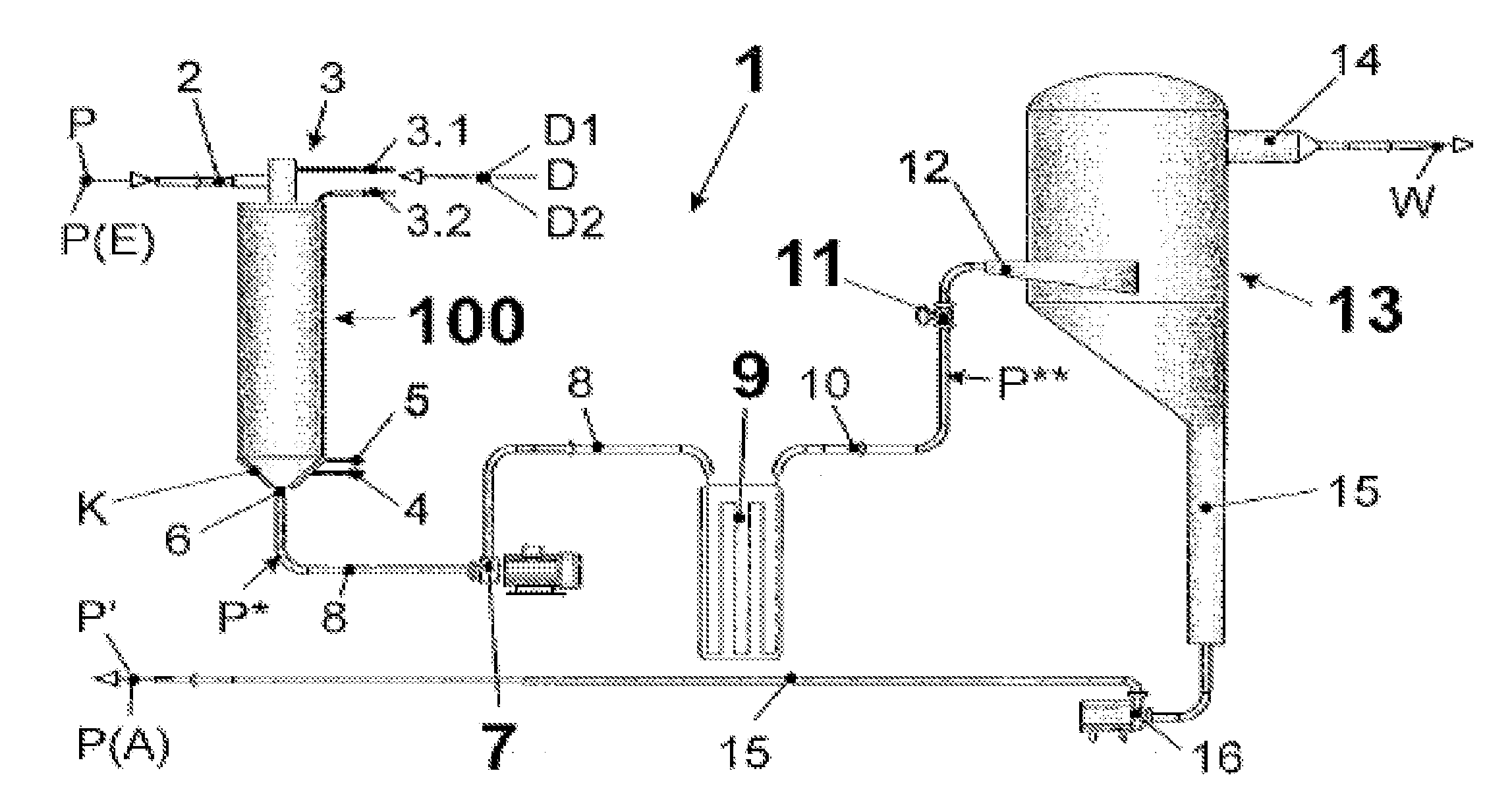
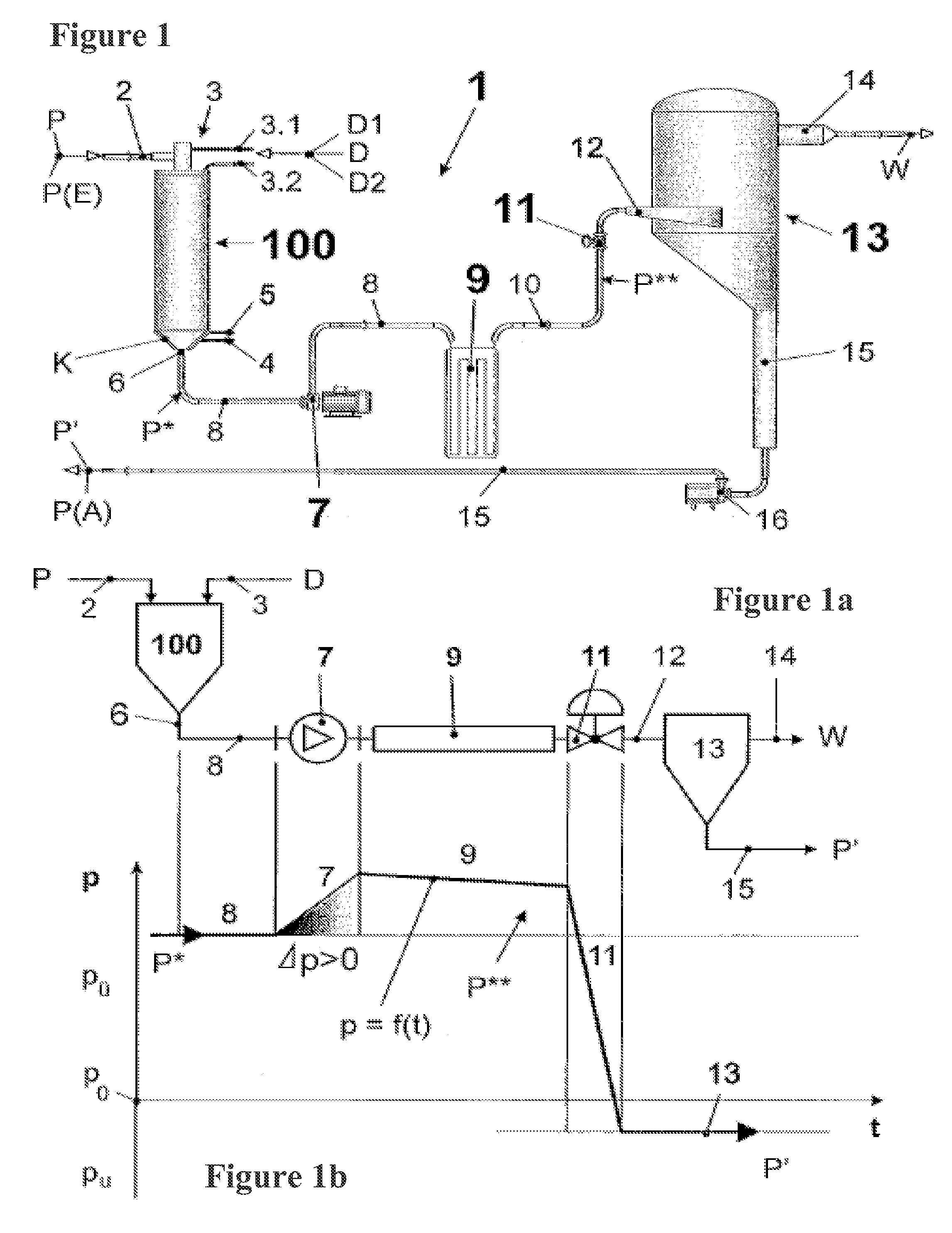
[0056]Due to the system characteristics of the UHT system 1 in the first embodiment as described above, the process characteristic according to the invention can be implemented that consists of the fact that the heated food product P*, before its heat maintenance as seen in the flow direction, undergoes a predetermined pressure increase Δp at a predetermined, unchanging location with the goal described above. This location, independently of fluctuations in operating conditions and due to the special displacement pump characteristic that achieves a decoupling of the system pressures p upstream and downstream of the displacement pump 7, is permanently at the suction-side inlet of the displacement pump 7 and thus, due to the preferably narrow and direct connection of the latter to infusion chamber 100, also at outlet 6.
second embodiment
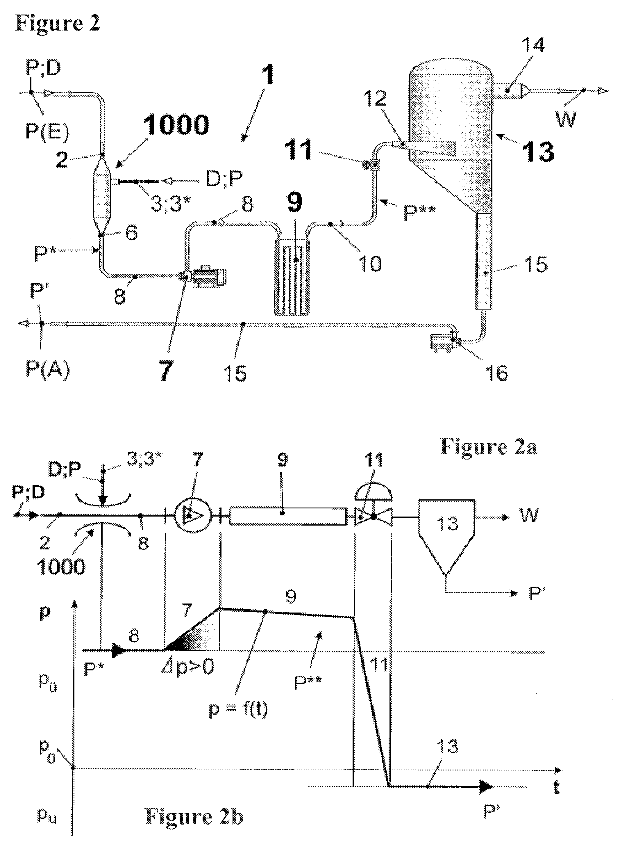
[0057]the UHT system 1 according to the invention (FIGS. 2, 2a, 2b) differs from the first shown in FIGS. 1, 1a, and 1b in that the mechanism in which the food product P to be treated is subjected to direct heating by means of introduction of steam D is now implemented according to the invention as an injector 1000. The other components of the UHT system 1 as shown in FIG. 1 are, insofar as they do not directly belong to infusion chamber 100, embodied identically in the second embodiment and have the same corresponding effects there. We will therefore forego a description.
[0058]The injector 1000, in a first embodiment, has on the one hand an inlet 2 for the introduction of the food product P to be treated, which leaves it on the other hand at its outlet 6 as the heated food product P*. A steam inlet 3 is used to introduce the steam D needed for direct heating, whereby steam D flows into the food product P acting as the driving stream. This first embodiment is therefore characterized...
PUM
 Abstract
Description
Claims
Application Information