
Catalyst carrying fine metal particles and use thereof

a technology of catalysts and metal particles, which is applied in the direction of metal/metal-oxide/metal-hydroxide catalysts, physical/chemical process catalysts, cell components, etc., can solve the problems of insufficient deposition of precious metal elements, difficult production, and particle diameter, so as to reduce the use of precious metals, suppress the effect of cost increase and useful especially in cost performan

Active Publication Date: 2012-12-20
NORITAKE CO LTD
View PDF3 Cites 18 Cited by
  • Summary
  • Abstract
  • Description
  • Claims
  • Application Information

AI Technical Summary

Benefits of technology

[0011]Thus, this invention has been made in order to achieve the above-mentioned objective by a non-conventional method. It provides a catalyst carrying fine metal particles having a core-shell structure (a fine metal particle-carrying catalyst) that exhibits excellent catalytic activity while suppressing an increase in cost by reducing the usage of a precious metal. In addition, this invention provides a method for preferably producing a catalyst of such a structure. Moreover, this invention provides a fuel cell (typically, a PEFC) constituted with a catalyst of such a structure.
[0015]In particular, according to the production method disclosed herein, core particles formed of a non-precious metal are first prepared by reducing a compound containing a non-precious metal that has a higher tendency to ionize than that of a precious metal in a fluid reaction mixture (typically, in a dispersion, etc.,) in which a conductive carrier is present, but the desired precious metal is absent. Following this, to the fluid reaction mixture, a compound containing the desired precious metal element is added and this compound is reduced. This allows formation of a precious metal layer on the respective surfaces of the pre-formed core particles formed of the non-precious metal, with the precious metal layer having been deposited via reduction by the reduction process. In other words, by carrying out the two-step reductions, an extremely thin precious metal layer (typically, a 2 to 10-atom thick layer) can be formed on the surface of the core portion composed of the non-precious metal. Typically, a non-precious metal-precious metal alloy layer is formed between the core portion formed of a non-precious metal and the outermost precious metal layer.
[0021]According to a production method comprising such processes, in the first reduction process to form the core portions (core particles), a prescribed reducing agent is added to the fluid reaction mixture and after the formation of the core particles, to the same fluid reaction mixture, is added a compound containing a precious metal element that is more readily reducible as compared to the non-precious metal. This allows efficient formation of fine metal particles having a desired core-shell structure.
[0025]With a fine metal particle-carrying catalyst of such a structure, the usage of a precious metal has been reduced and it is useful especially in terms of cost performance.
[0026]Preferably, the fine metal particles are characterized to have an average particle diameter of 3 nm to 15 nm based on electron microscopy analysis. By comprising fine metal particles of such a core-shell structure, it enables suppression of a cost increase while exhibiting high catalytic activity. Especially preferred is a catalyst carrying core-shell structured fine metal particles comprising a thin precious metal layer that is an approximately 2 to 10-atom thick layer.
[0027]In another preferred embodiment, the fine metal particle-carrying catalyst disclosed herein is characterized by that the shell portion of the respective fine metal particles is formed of a metal belonging to the platinum group (platinum, rhodium, palladium, etc.,) and the core portion of the fine metal particles is formed of a metal belonging to the iron group (nickel, iron, cobalt, etc.). Core-shell structured fine metal particles formed of such a combination of a precious metal and a non-precious metal allows to achieve a good cost reduction while exhibiting excellent catalytic activity.

Problems solved by technology

With catalyst particles constituted with core particles obtained by these methods and a precious metal element present on the surfaces of these core particles, there exist problems such as too large a particle diameter (e.g., displacement plating), insufficient deposition of the precious metal element on the core particle surfaces (e.g., spattering or vacuum deposition), etc., and thus, it is difficult to produce, on a carrier of a carbon, etc., fine metal particles having a core-shell structure suitable for achieving the aforementioned objective.

Method used

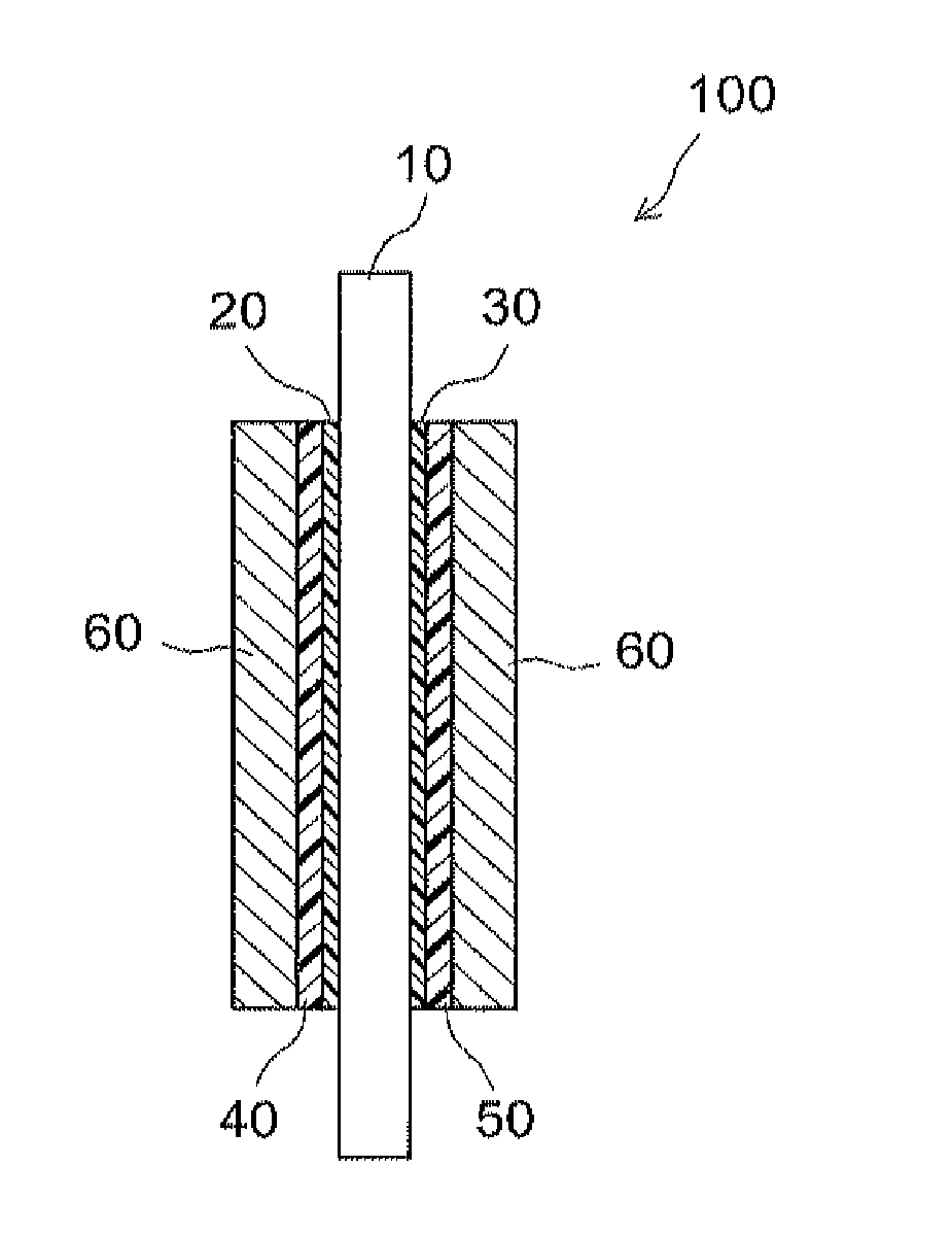

Image

  • Catalyst carrying fine metal particles and use thereof
  • Catalyst carrying fine metal particles and use thereof
  • Catalyst carrying fine metal particles and use thereof

Examples


example 1

[0076]As a non-precious metal, nickel was used and as a compound containing nickel, a nickel salt, nickel(II) chloride hexahydrate (NiCl2.6H2O) was used. Here, 1.2 g of nickel(II) chloride hexahydrate (NiCl2.6H2O) was dissolved in 7 mL of pure water to prepare a 1 M aqueous nickel chloride solution. On a hot plate stirrer, the aqueous nickel chloride solution was stirred at a temperature of 40° C. and a stirring speed of 250 rpm. Subsequently, to the stirring aqueous nickel chloride solution, were added 5.0 g of hydrazine hydrate (N2H4.H2O) as a complexing agent and 0.015 g of sodium citrate dihydrate (Na3C6H5O7.2H2O) as a reducing agent. After 1.5 g of carbon black (available from Cabot Corporation, product name: Vulcan XC72), which was a carbonaceous carrier, was added as a conductive carrier, 5.0 g of 50 weight % aqueous sodium hydroxide solution was added as a pH adjusting agent until around pH 9.

[0077]Here, before adding a precious metal to the aqueous solution, nickel chloride...

example 2

[0080]Here, an aqueous solution was prepared in the same manner as Sample 1 and after reducing the compounds in the aqueous solution, precipitated particles were collected. Here, however, hydrogen hexachloroplatinate(IV) hexahydrate was dissolved in the aqueous solution immediately (at about 0 minute to 20 minutes in this case) after adding the reducing agent to the aqueous nickel hydroxide solution. Hereinafter, the fine metal particle-carrying catalyst obtained by this process is referred to as Sample 2.

example 3

[0081]In this example, too, an aqueous solution was prepared in the same manner as Sample 1 and after reducing the compounds in the aqueous solution, precipitated particles were collected. Here, however, hydrogen hexachloroplatinate(IV) hexahydrate was dissolved in the aqueous solution twenty hours after adding the reducing agent to the aqueous nickel hydroxide solution. Hereinafter, the fine metal particle-carrying catalyst obtained by this process is referred to as Sample 3.

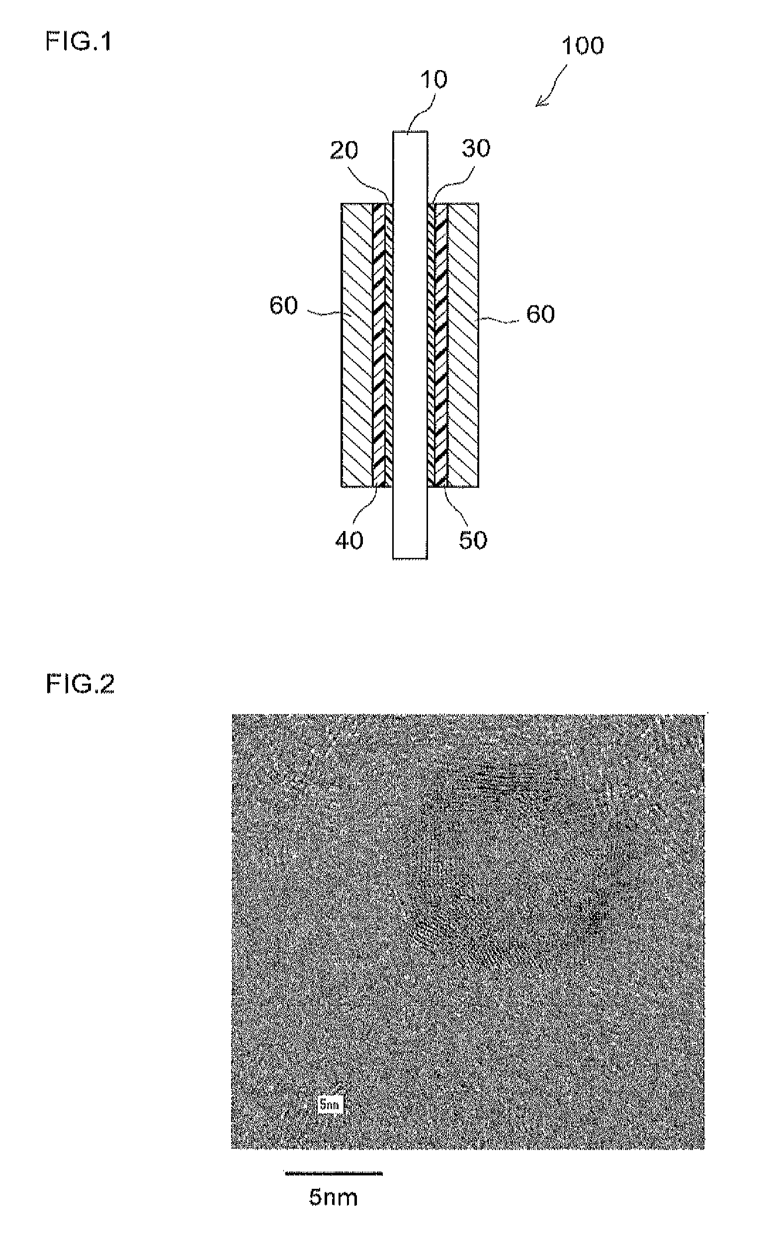
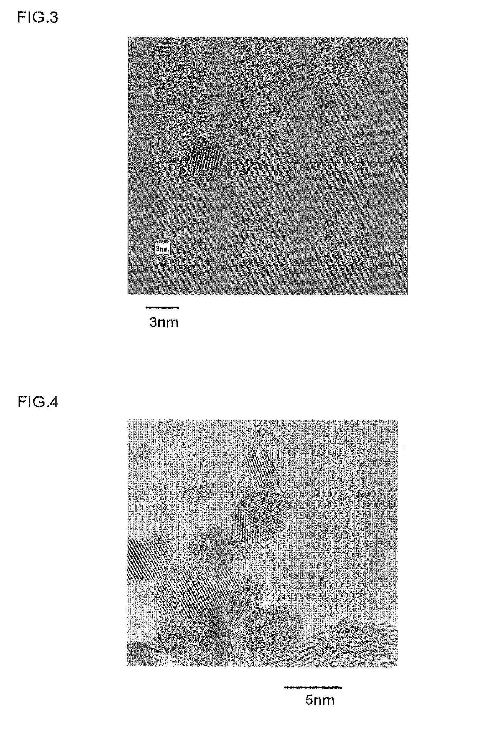
[0082]Samples 1 to 3 obtained by the production processes described above were analyzed by transmission electron microscopy (hereinafter, referred to as “TEM”). The resulting TEM photos are shown in FIGS. 2 to 4. FIG. 2 shows a TEM photo of Sample 1, FIG. 3 shows that of Sample 2 and FIG. 4 shows that of Sample 3. In these TEM photos, transmission images of metal particles supported by a conductive carrier particle can be observed. Of the observed metal particles, the dark parts correspond to platinum and the p...


PUM

PropertyMeasurementUnit
Particle diameteraaaaaaaaaa
Electrical conductoraaaaaaaaaa

Abstract

The production method according to the present invention includes a process for producing fine particles formed of a non-precious metal; a process for forming a shell of a precious metal on the respective surfaces of the fine particles of the non-precious metal; and a process for collecting a catalyst from a fluid reaction mixture. A fine metal particle-carrying catalyst prepared by such a production method includes fine non-precious metal particles as the cores thereby reducing the usage of a precious metal to achieve suppression of a cost increase. Since it includes a shell portion formed of a precious metal, it exhibits excellent catalytic activity.

Description

TECHNICAL FIELD[0001]The present invention relates to a fine metal particle-carrying catalyst comprising fine metal particles containing a catalytic precious metal on a carbon carrier as well as a method for producing the same. It also relates to use of the fine metal particle-carrying catalyst. In particular, it relates to a fuel cell in which the fine metal particle-carrying catalyst is used as an electrode catalyst. The present application claims priority to Japanese Patent Application No. 2010-044101 filed on Mar. 1, 2010 and the entire contents of the Japanese application are incorporated in this description by reference.BACKGROUND ART[0002]Catalysts obtained by depositing particles of catalytic platinum or other catalytic precious metals on the surface of an appropriate carrier (e.g., a carbon carrier) have been widely used for applications such as exhaust emission cleaning or as an electrode in a fuel cell. For example, as the electrode catalyst of a polymer electrolyte-based...

Claims


Application Information

Patent Timeline
IPC IPC(8): H01M4/90H01M4/92H01M4/88
CPCH01M4/8657Y02E60/50H01M4/926H01M4/92B01J20/3293B01J23/89B01J37/16B01J2523/828B01J35/51
Inventor ITO, MASAAKI
Owner NORITAKE CO LTD
Learn More