Organic light emitting diode display and manufacturing method thereof

a technology of light-emitting diodes and organic materials, which is applied in the direction of basic electric elements, solid-state devices, chemistry apparatuses and processes, etc., can solve the problems of deterioration of the quality of the oled display, and achieve the effects of improving the adhesion between the overcoat and the patterned metal sheet, prolonging the time of moisture absorption, and increasing the moisture permeation path

Active Publication Date: 2012-12-27
SAMSUNG DISPLAY CO LTD +1
View PDF2 Cites 33 Cited by
  • Summary
  • Abstract
  • Description
  • Claims
  • Application Information

AI Technical Summary

Benefits of technology

[0032]Thus, adhesion between the overcoat and the patterned metal sheet can be improved by increasing the area where the patterned metal sheet contacts the adhesive layer of the overcoat so that the life-span of the organic light emitting diode can be improved by completely blocking the permeation of external moisture.
[0033]Further, the protrusions and the oxide silicon particles are formed in the bottom surface of the patterned metal sheet and have a regular shape so that the entire surface of the thin film encapsulation layer can be uniformly reformed, thereby equalizing the life-span of the respective organic light emitting diodes.
[0034]In addition, the moisture permeation path is increased by using the patterned metal sheet having the protrusion and depression portions so that the moisture absorption time can be extended, thereby improving the life-span of the organic light emitting diode.
[0035]In addition, chemical treatment of a silane coupling agent for improving adhesion between the overcoat formed of the organic layer and the metal sheet is not required, and accordingly additional contamination due to outgas can be prevented.
[0036]Further, surface uniformity can be improved by forming the patterned metal sheet having the regular-shaped protrusion and depression portions in the thin film encapsulation layer. Accordingly, when the filling material is filled, the filing material applies uniform pressure to the entire surface, thereby preventing damage to the organic light emitting diode due to pressure.

Problems solved by technology

However, because the organic emission layer is sensitive to external factors such as moisture or oxygen, when the organic emission layer is exposed to moisture and oxygen, the quality of the OLED display deteriorates.

Method used


Image

  • Organic light emitting diode display and manufacturing method thereof
  • Organic light emitting diode display and manufacturing method thereof
  • Organic light emitting diode display and manufacturing method thereof

Examples


Embodiment Construction

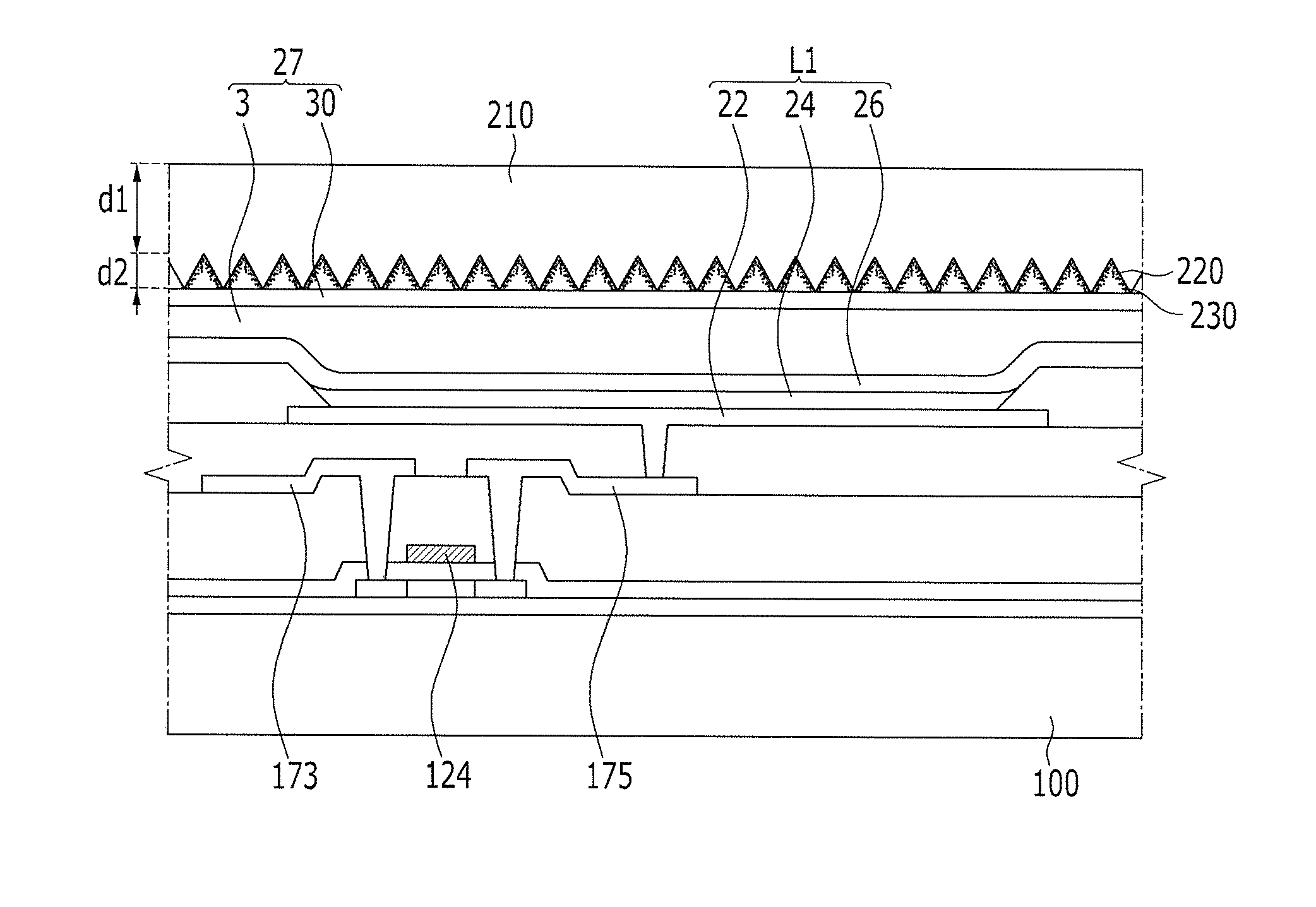
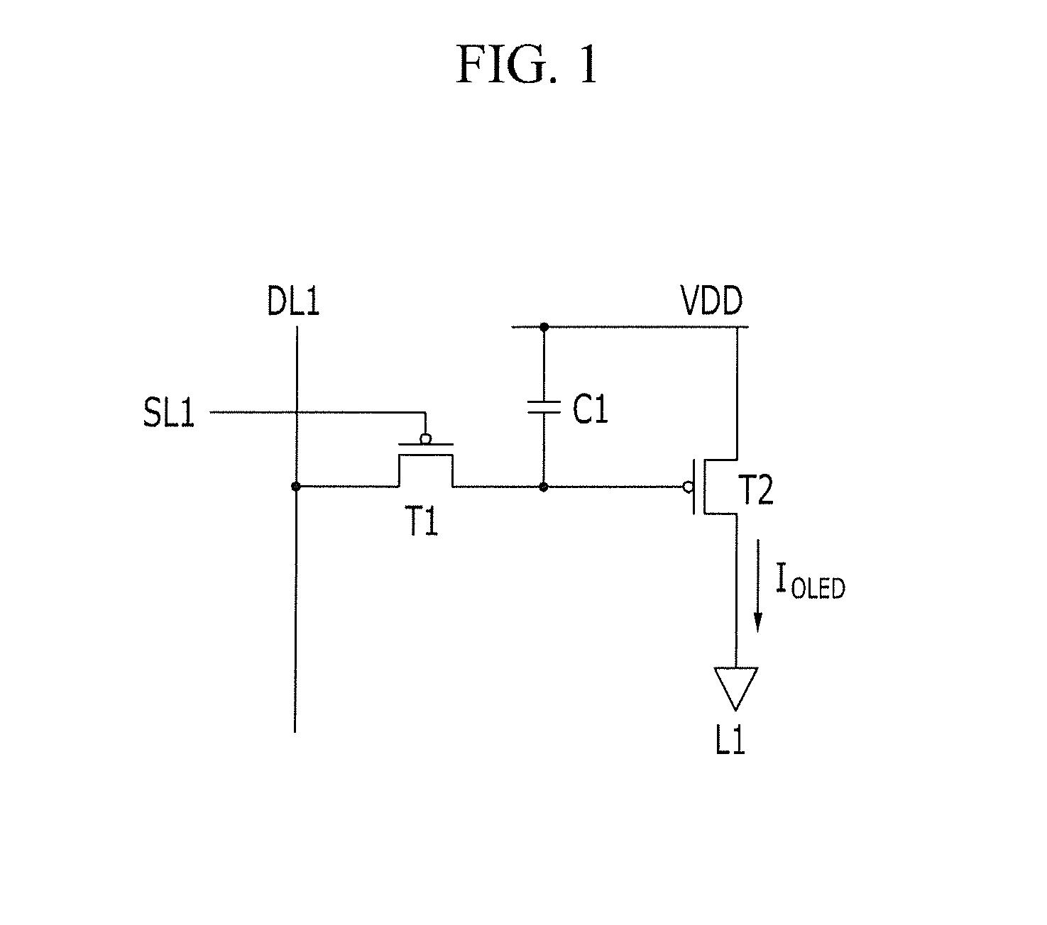
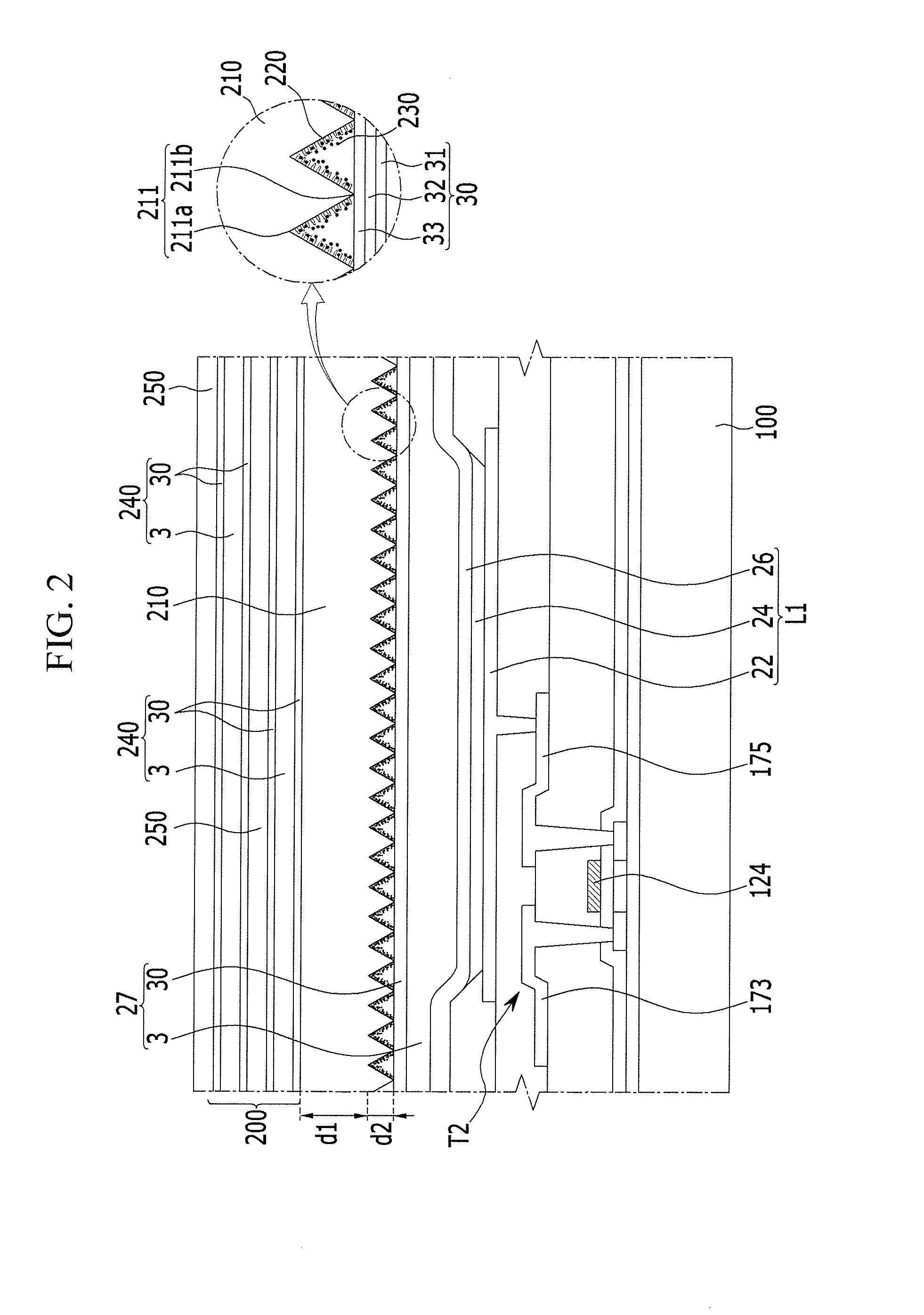
[0042]The present invention will be described hereinafter with reference to the accompanying drawings, in which exemplary embodiments of the invention are shown. As those skilled in the art would realize, the described embodiments may be modified in various different ways, all without departing from the spirit or scope of the present invention.

[0043]Accordingly, the drawings and description are to be regarded as illustrative in nature and not restrictive. Like reference numerals designate like elements throughout the specification.

[0044]In addition, the size and thickness of each component shown in the drawings are arbitrary, and are used to enhance understanding and for ease of description, but the present invention is not limited thereto.

[0045]In the drawings, the thickness of layers, films, panels, regions, etc., are exaggerated for clarity. In the drawings, for understanding and ease of description, the thicknesses of some layers and areas are exaggerated. It will be understood ...


PUM


Abstract

An OLED display according to an exemplary embodiment includes: a substrate; an organic light emitting diode formed on the substrate; an overcoat covering the organic light emitting diode; and a patterned metal sheet attached on the overcoat and having a plurality of protrusion and depression portions. A plurality of protrusions may be formed in a bottom surface of the patterned metal sheet where the protrusion and depression portions of the patterned metal sheet and the overcoat face each other.

Description

CROSS-REFERENCE TO RELATED APPLICATION[0001]This application claims priority to and the benefit of Korean Patent Application No. 10-2011-0060249 filed in the Korean Intellectual Property Office on Jun. 21, 2011, the entire contents of which are incorporated herein by reference.BACKGROUND[0002]1. Technical Field[0003]The described technology relates generally to an organic light emitting diode (OLED) display and a manufacturing method thereof.[0004]2. Description of Related Art[0005]Unlike the liquid crystal display (LCD), an organic light emitting diode (OLED) display does not require a separate light source, thereby making it possible to be implemented as a slim and lightweight display. Furthermore, as the organic light emitting diode display has high quality characteristics such as lower power consumption, high luminance, and short response time, it has been spotlighted as a next generation display device.[0006]The OLED includes a plurality of light emitting diodes, each having a ...

Claims


Application Information

Patent Timeline
Patent Type & Authority Applications(United States)
IPC IPC(8): H01L51/52H01L51/56
CPCH10K50/846H10K50/844C09K15/02H01L23/26H10K50/8426H10K50/84
Inventor SON, JUNG-HYUNKIM, HOONNAM, KIE HYUN
Owner SAMSUNG DISPLAY CO LTD
Why Eureka
Try Eureka