

Fuel injection control system for internal combustion engine
- Summary
- Abstract
- Description
- Claims
- Application Information
AI Technical Summary
Benefits of technology
Problems solved by technology
Method used
Image

Examples
first embodiment
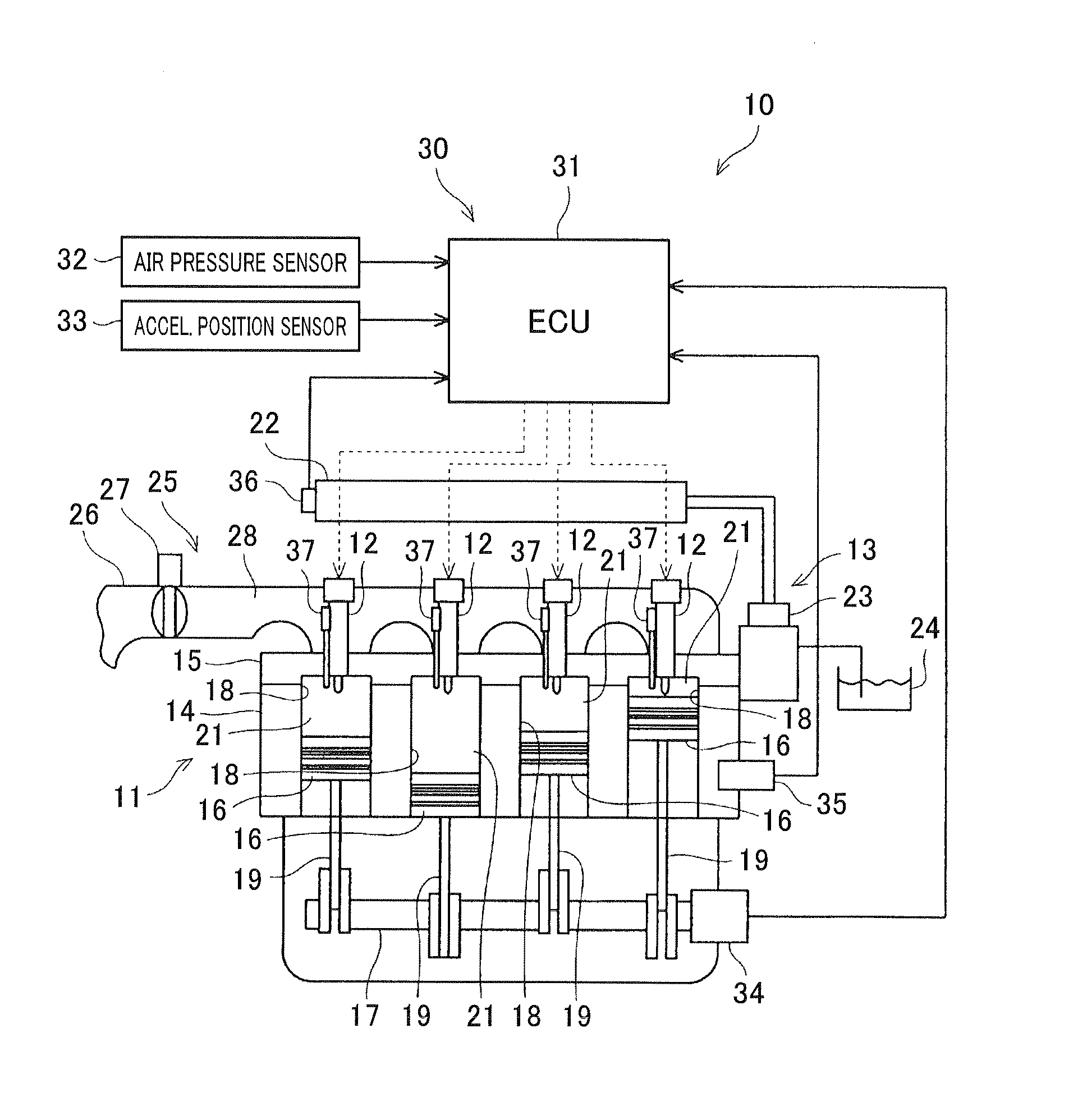
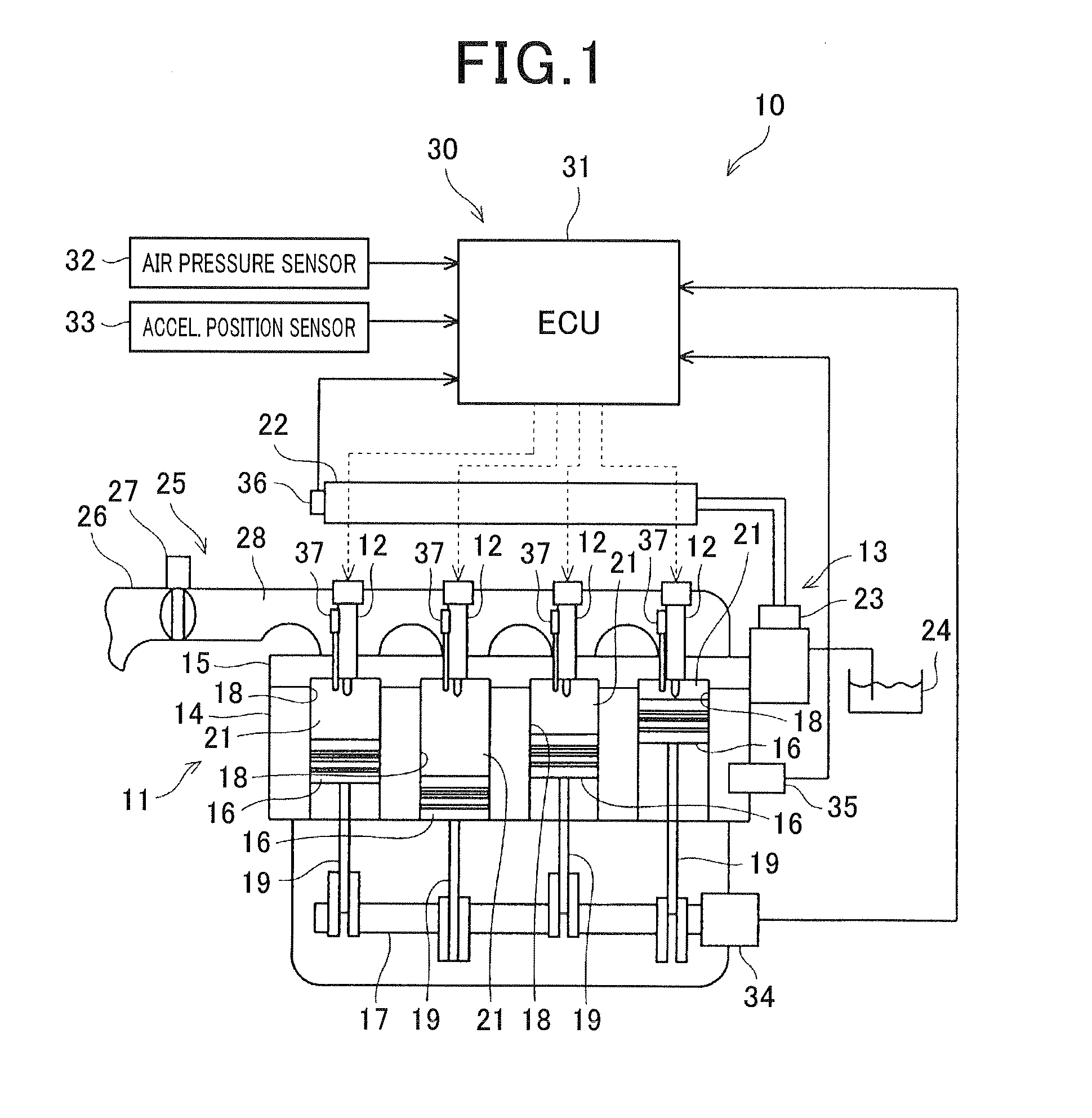
[0042]Referring to the drawings, wherein like reference numbers refer to like parts in several views, particularly to FIG. 1, there is shown a diesel engine system 10 which is engineered as a common rail multi-fuel injection system for internal combustion diesel engines mounted in automotive vehicles.
[0043]The diesel engine system 10 includes a diesel engine 11, fuel injectors 12, and a fuel supply system 13. The diesel engine 11 is equipped with a cylinder block 14, a cylinder head 15, pistons 16, and a crankshaft 17. The cylinder block 14 has a plurality of cylinders 18 formed therein. The cylinder head 15 is mounted on an end surface of the cylinder block 14. Each of the pistons 16 is disposed within one of the cylinders 18 to be reciprocable in an axial direction of the cylinders 18. The crankshaft 17 is disposed inside the cylinder block 14 in mechanical connection with the pistons 16 through a connecting rod 19. The reciprocating motion of the pistons 16 is converted into rot...
second embodiment
[0085]The above operations of the diesel engine system 10 of the second embodiment will be described below with reference to a flowchart of a fuel injection control program, as illustrated in FIG. 18.
[0086]The program is initiated by the ECU 31 after step S108 of FIG. 3.
[0087]First, in step S201, the flow velocity determining circuit 51 acquires an output of the speed sensor 34 indicating the speed of the crankshaft 17 of the engine 11. The routine proceeds to step S202 wherein the flow velocity determining circuit 51 calculates the flow velocity of a swirl of air inducted into the combustion chamber 21. Specifically, the flow velocity determining circuit 51 determines an angular velocity S of the swirl which correlates with the speed of rotation of the crankshaft 17.
[0088]The routine proceeds to step S203 wherein the pilot-to-pilot injection interval determining circuit 52 determines a time interval ΔT between every adjacent two of a sequence of events of the pilot injection based ...
fourth embodiment
[0115]FIG. 21 illustrates the fuel injection control device 80 of the diesel engine system 10 of the The same reference numbers, as employed in the above embodiments, will refer to the same parts, and explanation thereof in detail will be omitted here.
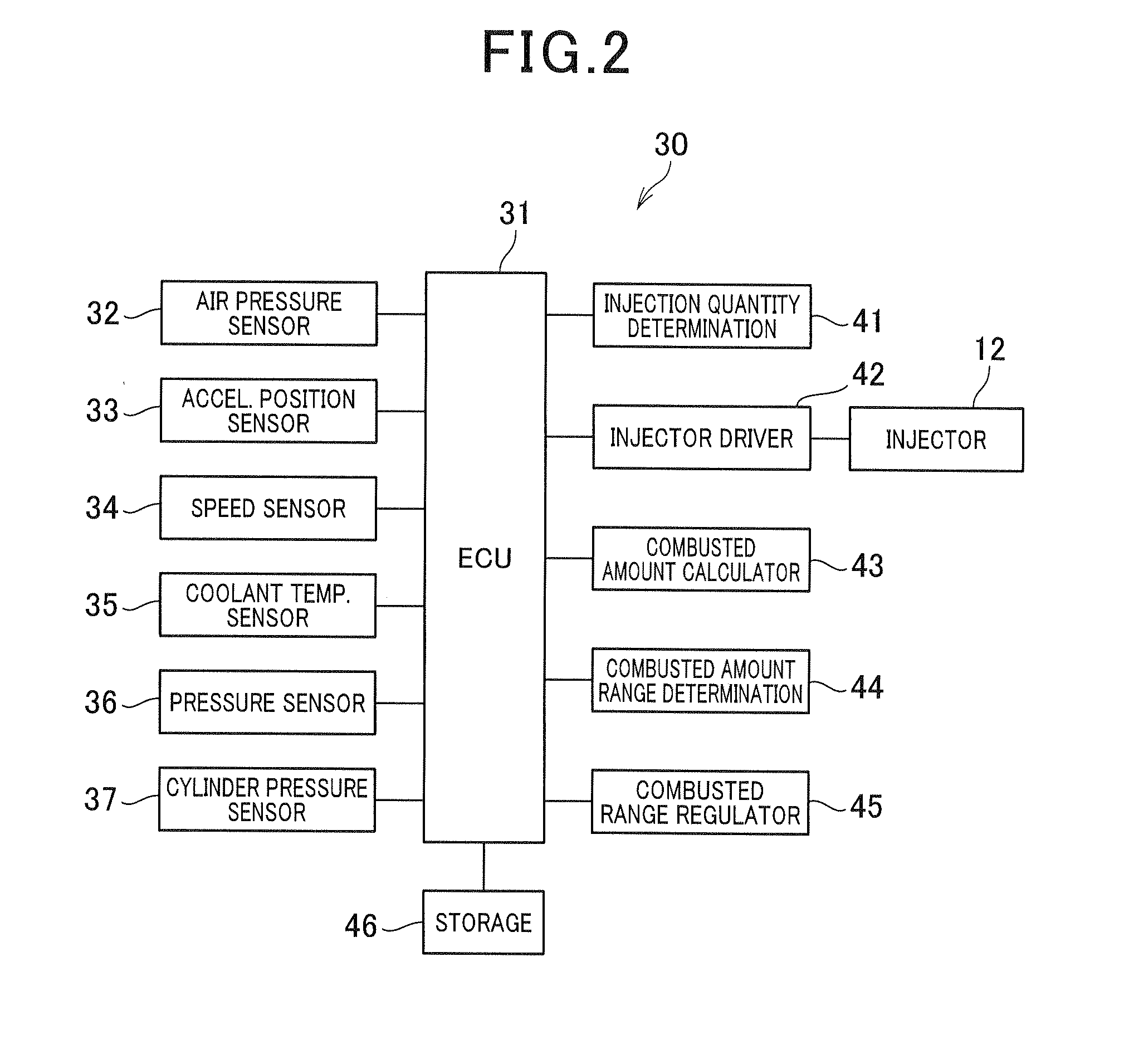
[0116]The fuel injection control device 80 is equipped with the ECU 31. The ECU 31 is coupled electrically with the atmospheric pressure sensor 32, the accelerator position sensor 33, the speed sensor 34, the coolant temperature sensor 35, and the pressure sensor 36.
[0117]The ECU 31 executes computer programs to functionally construct the injection quantity calculator 41, the injector driver 42, the cetane number determining circuit 81, and the pilot injection number controller 82. The ECU 31 is also coupled electrically to the storage device 46. The ECU 31 does not has the cylinder pressure sensor 37 used in the first and second embodiments. The injection quantity calculator 41, the injector driver 42, the cetane number determining c...
PUM
 Abstract
Description
Claims
Application Information