Apparatus and method for formation of foil-shaped stent struts

Inactive Publication Date: 2013-01-03
ABBOTT CARDIOVASCULAR
View PDF27 Cites 7 Cited by
  • Summary
  • Abstract
  • Description
  • Claims
  • Application Information

AI Technical Summary

Benefits of technology

[0016]The invention is directed to an improved apparatus and method for the treatment of an intravascular stent formed from a metal alloy. The invention is directed to an apparatus and method for passing an abrasive slurry over the struts of an intravascular stent in order to remove a portion of the stent struts to form an airfoil shape. More particularly, the transverse cross-section of one more struts of the stent have a shape that resembles an airfoil or a hydrofoil which will reduce turbulent blood

Problems solved by technology

Expandable stents, such as wire mesh, serpentine, and corrugated ring designs, for example, do not possess uniformly solid tubular walls.
A roughened outer surface may result in increased frictional obstruction during insertion and excess drag during travel to the stenotic site as well as damaging the endothelium lining of the vessel wall.
A rough finish may also cause damage to the underlying inflation balloon.
Laser cutting, however, typically is at high temperature and often leaves debris and slag material attached to the stent.
Such material, if left on a stent, would render the stent unacceptable for implantation.
Grinding, vibration, and tumbling techniques ar

Method used


Image

  • Apparatus and method for formation of foil-shaped stent struts
  • Apparatus and method for formation of foil-shaped stent struts
  • Apparatus and method for formation of foil-shaped stent struts

Examples


Embodiment Construction

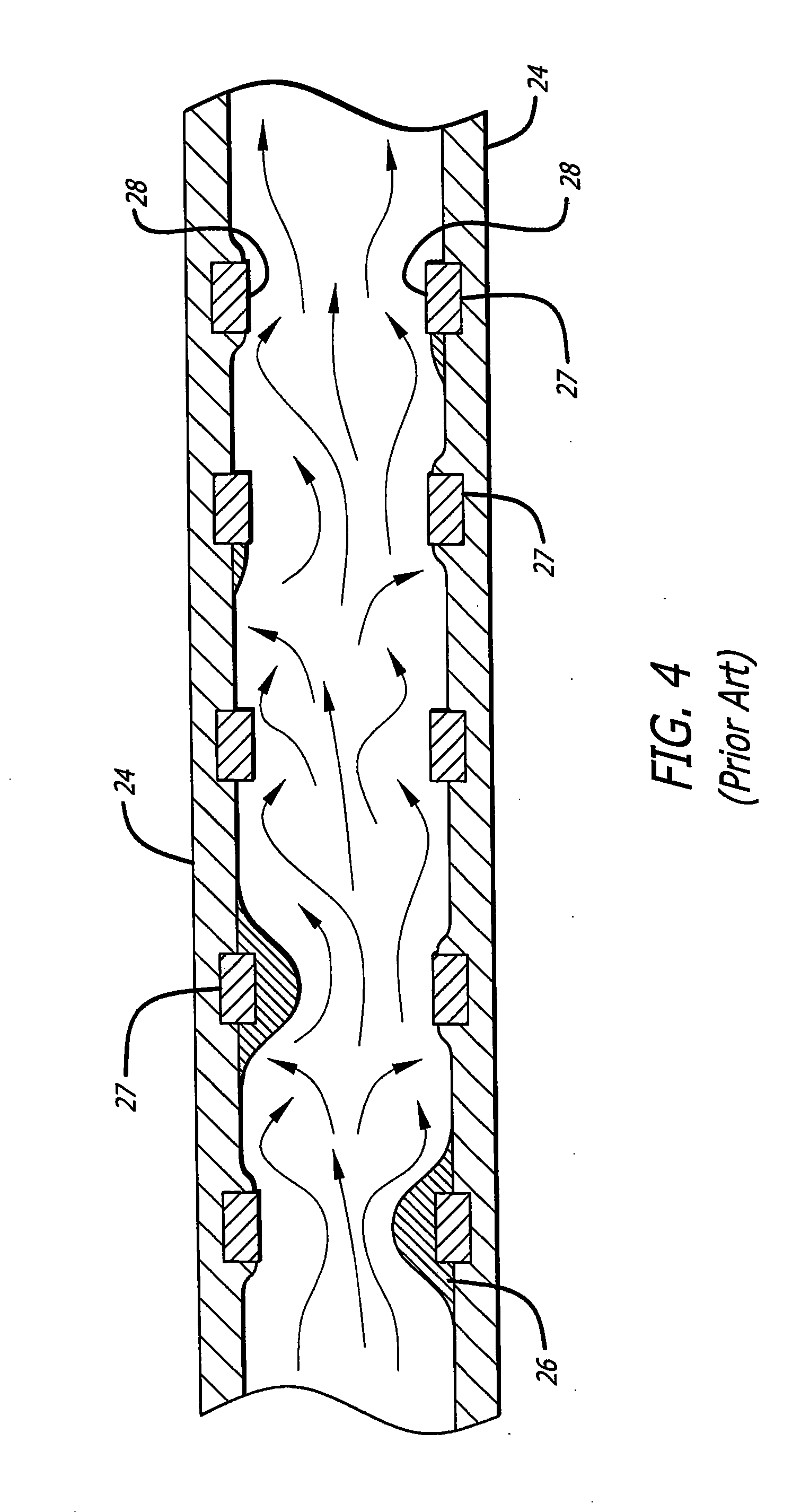
[0029]The present invention stent improves on existing stents by providing a longitudinally flexible stent having a uniquely designed pattern and novel interconnecting members. In addition to providing longitudinal flexibility, the stent of the present invention also provides radial rigidity and a high degree of scaffolding of a vessel wall, such as a coronary artery. The present invention stent is processed so that it is more hemodynamically compatible and causes less blood flow turbulence when implanted in an artery.

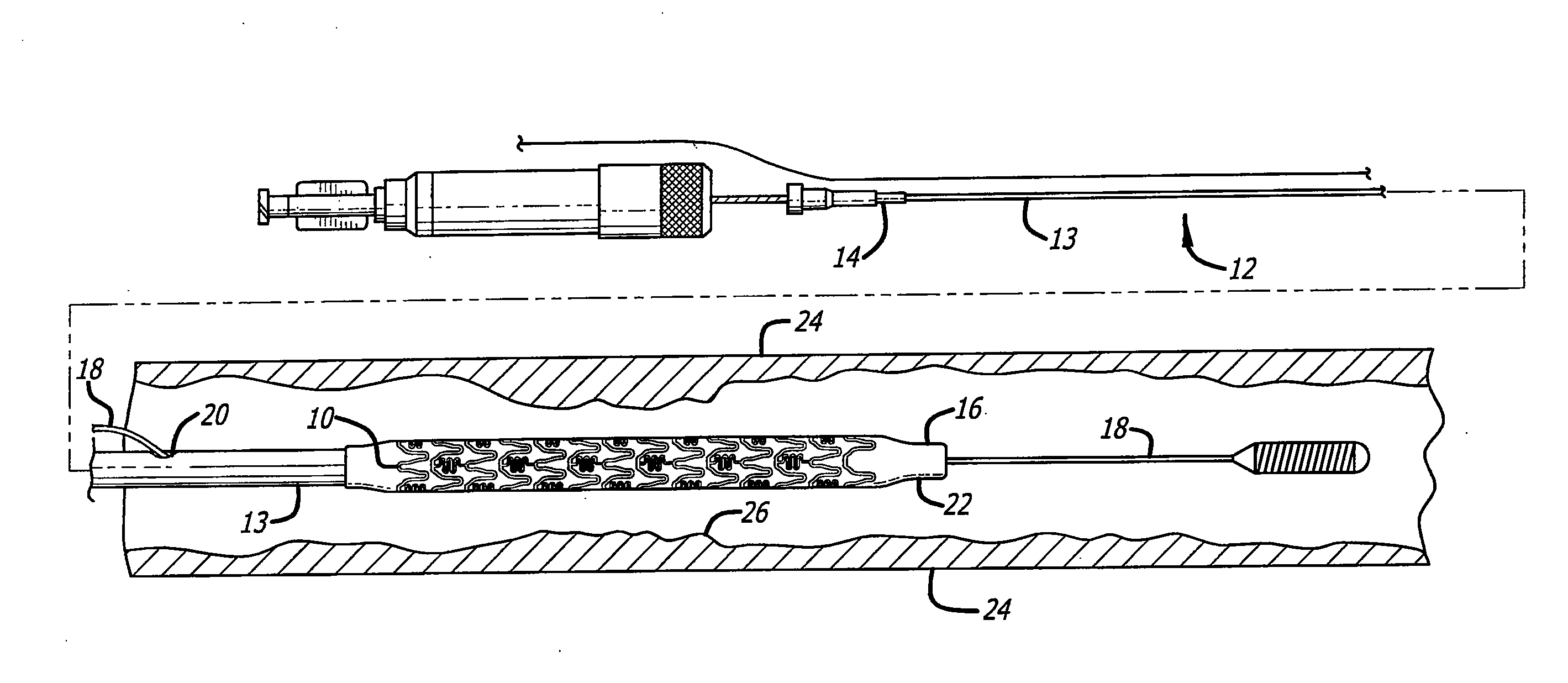
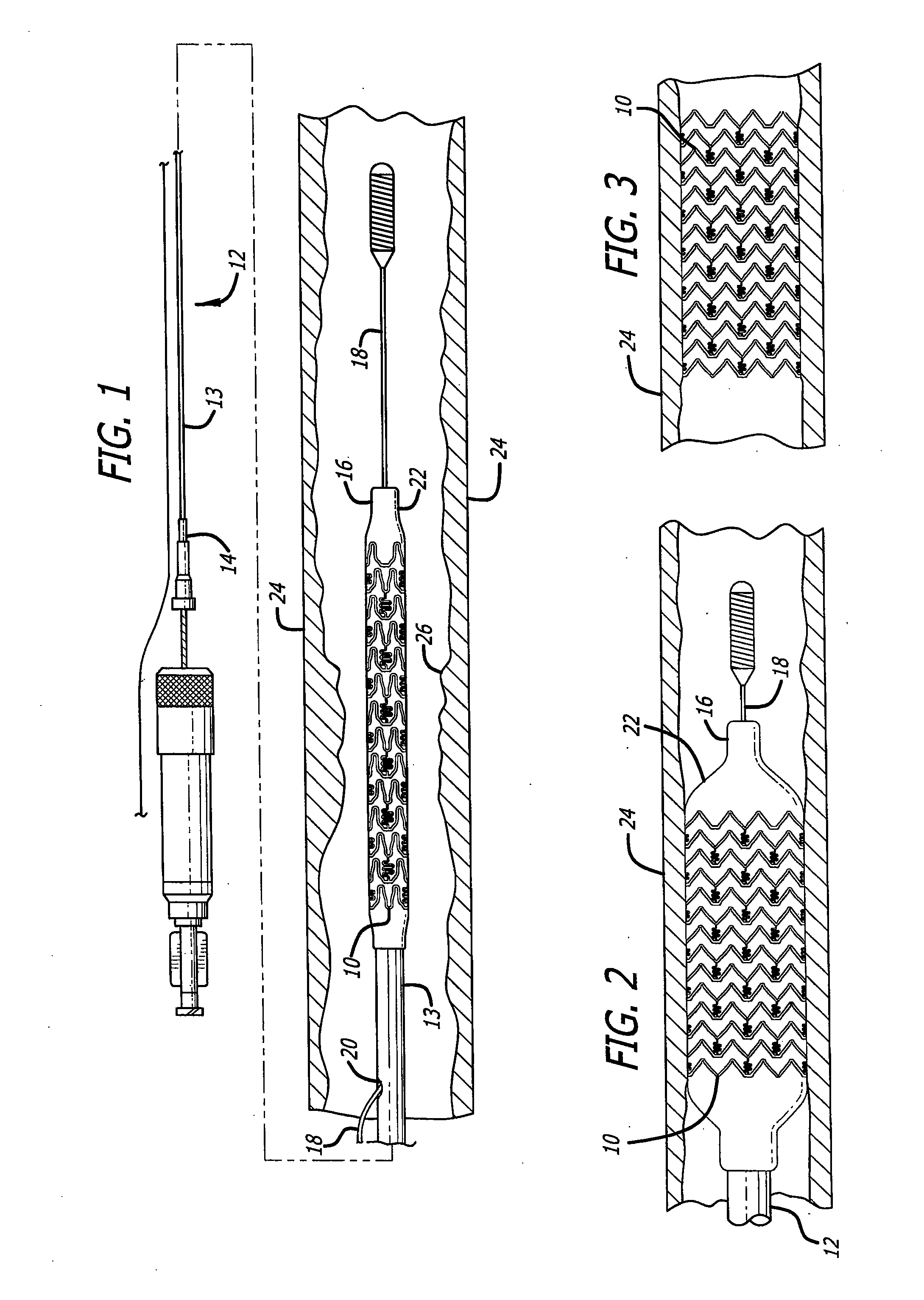
[0030]Turning to the drawings, FIG. 1 depicts a prior art stent 10 mounted on a conventional catheter assembly 12 which is used to deliver the stent and implant it in a body lumen, such as a coronary artery, peripheral artery, or other vessel or lumen within the body. The catheter assembly includes a catheter shaft 13 which has a proximal end 14 and a distal end 16. The catheter assembly is configured to advance through the patient's vascular system by advancing over a...


PUM

PropertyMeasurementUnit
Lengthaaaaaaaaaa
Lengthaaaaaaaaaa
Lengthaaaaaaaaaa

Abstract

A device and method is disclosed for reducing turbulent blood flow over stent struts of an intravascular stent implanted in, for example, a coronary artery. An abrasive slurry is passed over the struts of an intravascular stent in order to remove a portion of the stent struts to form an airfoil shape. When the stent having airfoil-shaped struts is implanted in an artery, the flow of blood over the airfoil shape will reduce the likelihood of turbulent blood flow and thereby will reduce the likelihood of turbulent blood flow and thereby reduce the likelihood of a buildup in plaque or injury to the vessel wall.

Description

BACKGROUND[0001]The invention relates generally to providing an apparatus for using an abrasive slurry for the removal of metal on products made from metals. More particularly, the invention relates to an apparatus for and method of using an abrasive slurry on medical devices made of titanium, stainless steel, tungsten, nickel-titanium, tantalum, cobalt-chromium-tungsten, cobalt-chromium, and the like to form a more hemodynamically compatible device.[0002]While a wide range of products or devices can be made from the listed metal alloys for use with the present invention, medical devices are particularly suitable due to the biocompatible characteristics of these alloys. Thus, for example, implantable medical devices or devices that are used within the human body are particularly suitable and can be made from these alloys that have been treated in accordance with the present invention. More particularly, and as described in more detail herein, intravascular stents can be made from th...

Claims


Application Information

Patent Timeline
IPC IPC(8): B24C1/00
CPCB24C1/083A61F2/915A61F2230/0004A61F2002/91566A61F2002/068
Inventor VON OEPEN, RANDOLFEHRENREICH, KEVIN J.
Owner ABBOTT CARDIOVASCULAR
Why Eureka
Try Eureka