Blanket for offset printing and manufacturing method therefor

Active Publication Date: 2013-01-10
LG CHEM LTD
View PDF4 Cites 15 Cited by
  • Summary
  • Abstract
  • Description
  • Claims
  • Application Information

AI Technical Summary

Benefits of technology

[0021]As set forth above, the exemplary embodiment of the present invention comprises the silicon-based resin in which at least one of the hardness value, the fluorine content value, and the silicon oil content value within at least two surface printin

Problems solved by technology

However, the photolithography process manufactures predetermined pattern masks and repeats a chemical etching process and a stripping process, such that the manufacturing process is complicated and a large amount of chemical wastes harmful to environment occur.
This increases manufacturing costs, thereby degrading competitiveness of products.
The blanket manufactured as described above may have a limitation in manufacturing to have a uniform thickness and is difficult to mass produce as a pilot scale.
Further, the cushion layer serves to compensate the diff

Method used


Image

  • Blanket for offset printing and manufacturing method therefor
  • Blanket for offset printing and manufacturing method therefor
  • Blanket for offset printing and manufacturing method therefor

Examples


example 1

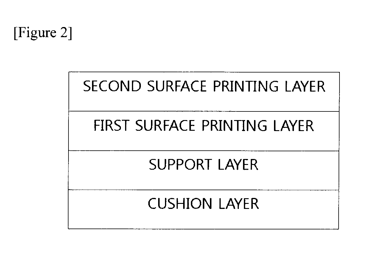
At Least Two Surface Printing Layers Having Different Hardness Value

[0082]The cushion layer forming mixture was prepared by adding 100 parts by weight of the liquid-phase silicon resin and 10 parts by weight of the hollow microsphere (MFL80CA manufactured by Matsumoto Yushi-Seiyaku Co., Ltd.), mixing and uniformly dispersing them, and then, further adding 10 parts by weight of hardener.

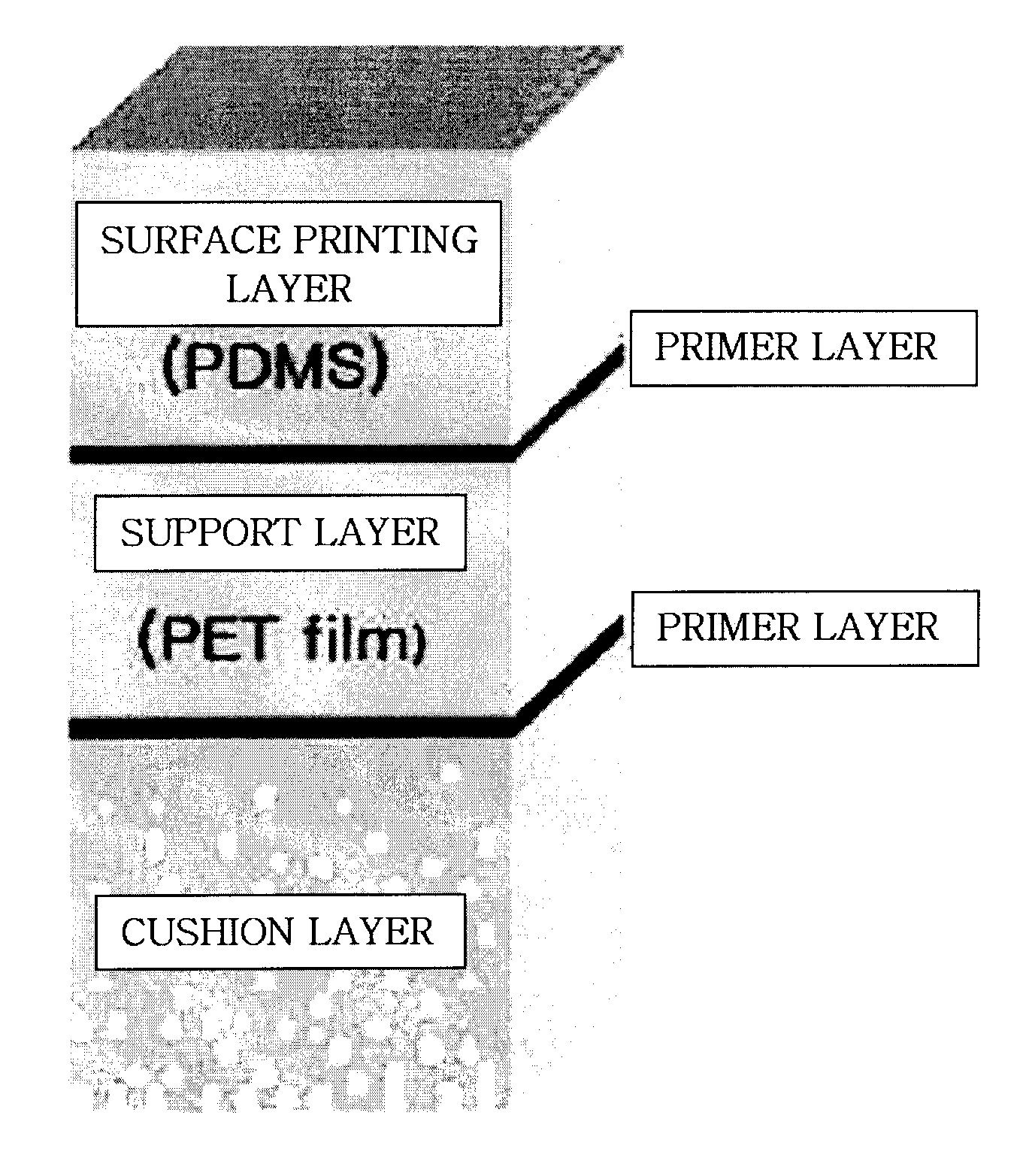
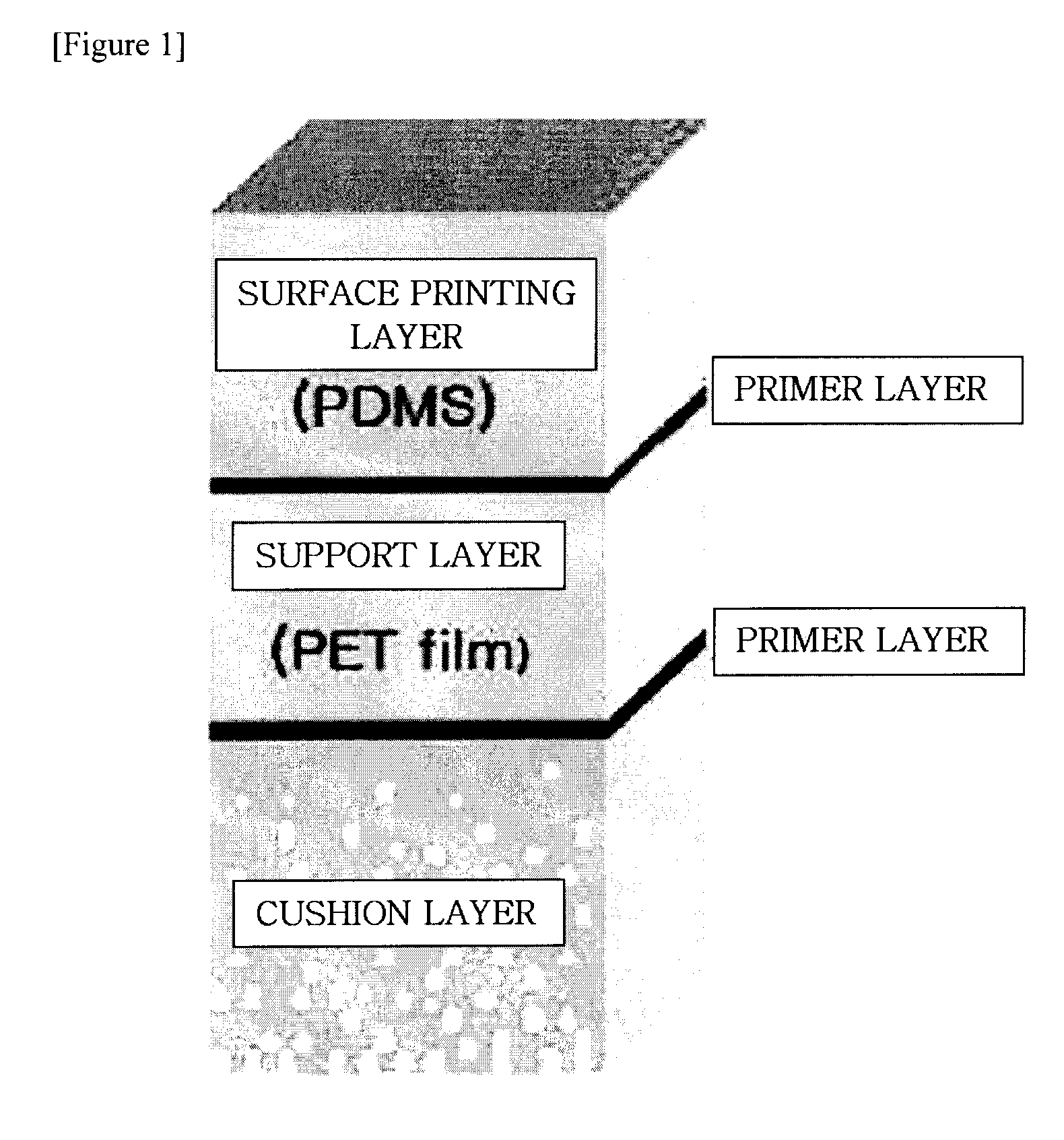
[0083]Next, after the tension was applied to the polyethyleneterephthalate (PET) base film having about 0.35 mm on the surface plate of which the level is maintained in a manner of pulling both ends thereof, the PET closely contacting the surface plate in vacuum in order to completely closely contacting the surface plate and then, the vacuum was removed after coating so as not to leave the marks of the vacuum hole of the PET.

[0084]Then, the cushion layer forming mixture was uniformly applied to an area of about 120 cm×150 cm on one surface of the base by using an applicator. The cushion layer having a...

example 2

At Least Two Surface Printing Layers According to Presence or Absence of Fluorine Group

[0091]After the printing layer made by comprising the fluorine-based PDMS containing resin and vinyl terminated trifluoro propyl methyl siloxane of 10 wt % manufactured by Gelest Inc., in KE1606 was applied to the first surface printing layer and was hardened at normal temperature for three days, the blanket for printing was completed by the same manner as Example 1, except for preparing the mixture by mixing and uniformly dispersing the hardener of 10 parts by weight for 100 parts by weight of the silicon resin to the second surface printing layer and applying the mixture to the first surface printing layer by using the applicator.

example 3

At Least Two Surface Printing Layers According to Presence or Absence of Silicon Oil

[0092]After the mixed resin of the silicon oil of 5 wt % for the PDMS (KE1606 / CAT-RG 10:1 manufactured by Shin-Etsu Chemical Co., Ltd.) was applied to the first surface printing layer and was hardened at normal temperature for three days, the blanket for printing was completed by the same manner as Example 1, except for preparing the mixture by mixing and uniformly dispersing the hardener of 10 parts by weight for 100 parts by weight of the silicon resin to the second surface printing layer and applying the applying to the first surface printing layer by using the applicator.


PUM


Abstract

The present invention relates to a blanket for offset printing and a manufacturing method thereof. The blanket for offset printing according to an exemplary embodiment of the present invention comprises a cushion layer, a support layer, and at least two surface printing layers, wherein the at least two surface printing layers comprise a silicon-based resin in which at least one of a hardness value, a fluorine group content value, and a silicon oil content value is different. The blanket for offset printing according to the exemplary embodiment of the present invention comprises the surface printing layer formed in at least two layers to prevent the surface printing layer from being swollen due to ink, thereby reducing a process waiting time and improving a process margin.

Description

TECHNICAL FIELD[0001]The present invention relates to a blanket for offset printing and a manufacturing method thereof, and more particularly, to a blanket for offset printing having characteristics of reduced swelling ratio and a manufacturing method thereof. This application claims priority from Korean Patent Application No. 10-2010-0024859 filed on Mar. 19, 2010 in the KIPO, the disclosure of which is incorporated herein by reference in its entirety.BACKGROUND ART[0002]Generally, electronic devices such as a liquid crystal display, a semiconductor device, or the like, are manufactured by forming patterns of multiple layers on a substrate. In order to form these patterns, a photolithography process has been mainly used up to now. However, the photolithography process manufactures predetermined pattern masks and repeats a chemical etching process and a stripping process, such that the manufacturing process is complicated and a large amount of chemical wastes harmful to environment ...

Claims


Application Information

Patent Timeline
IPC IPC(8): B41C3/08
CPCB41N10/04B41N2207/02B41N2210/14B41N2210/02B41N2210/04B41N2207/14B41N10/02
Inventor YOO, HONG-SIKKOO, BEOM-MOLEE, SOON-YEOLLEE, SEUNG-HEONPARK, JIN-YOUNG
Owner LG CHEM LTD
Why Eureka
Try Eureka