Laminate polishing pad

a polishing pad and laminate technology, applied in the field of laminate polishing pads, can solve the problems of peeling or displacement more likely to occur between the layers during polishing, peeling or displacement more likely to occur between the cushion layer and the polishing layer without through holes, and achieve the effect of effectively preventing peeling or gas blistering

Inactive Publication Date: 2013-01-10
ROHM & HAAS ELECTRONICS MATERIALS CMP HLDG INC
View PDF5 Cites 10 Cited by
  • Summary
  • Abstract
  • Description
  • Claims
  • Application Information

AI Technical Summary

Benefits of technology

[0039]In the laminate polishing pad of the invention, the back side of the polishing layer has the non-adhering region X continuously extending from a central region of the polishing layer to a peripheral end of the polishing layer, and/or the adhesive member has the non-adhering region Y continuously extending from a...

Problems solved by technology

Unfortunately, such a polyurethane foam sheet has insufficient cushioning properties and therefore can hardly apply uniform pressure to the entire surface of a wafer, though it has high local-planarization performance.
Unfortunately, conventional laminate polishing pads, which have layers bonded together with an adhesive or a pressure-sensitive adhesive, have a problem in which peeling or displacement is more likely to occur between the layers during polishing.
Unfortunately, the problem that pe...

Method used


Image

  • Laminate polishing pad
  • Laminate polishing pad
  • Laminate polishing pad

Examples


production example 1

Production of Polishing Layer

[0118]To a polymerization vessel were added 100 parts by weight of an isocyanate-terminated prepolymer (ADIPRENE L-325, manufactured by Chemtura Corporation) and 3 parts by weight of a silicone surfactant (SH-192, manufactured by Dow Corning Toray Silicone Co., Ltd.) and mixed. The mixture was adjusted to 80° C. and degassed under reduced pressure. Subsequently, the mixture was vigorously stirred with a stirring blade at a number of revolutions of 900 rpm for about 4 minutes in such a manner that air bubbles were incorporated into the reaction system. To the resulting mixture was added 26 parts by weight of 4,4′-methylenebis (o-chloroaniline) (IHARACUAMINE-MT, manufactured by IHARA CHEMICAL INDUSTRY CO., LTD.), which had been previously melted at 120°. The liquid mixture was stirred for about 1 minute and then poured into a loaf-shaped open mold (casting vessel). At the point when the liquid mixture lost its fluidity, it was placed in an oven, and subjec...

example 1

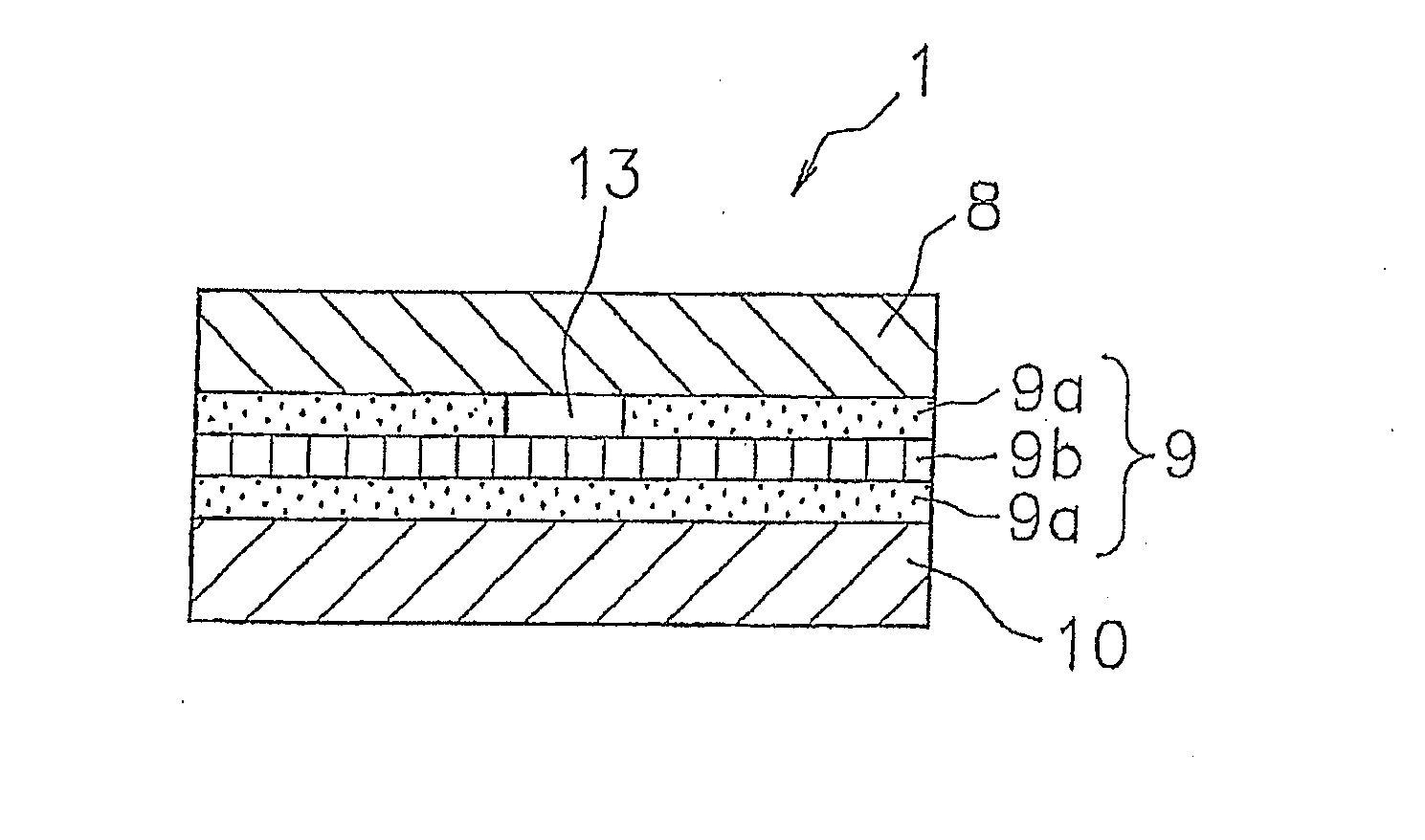
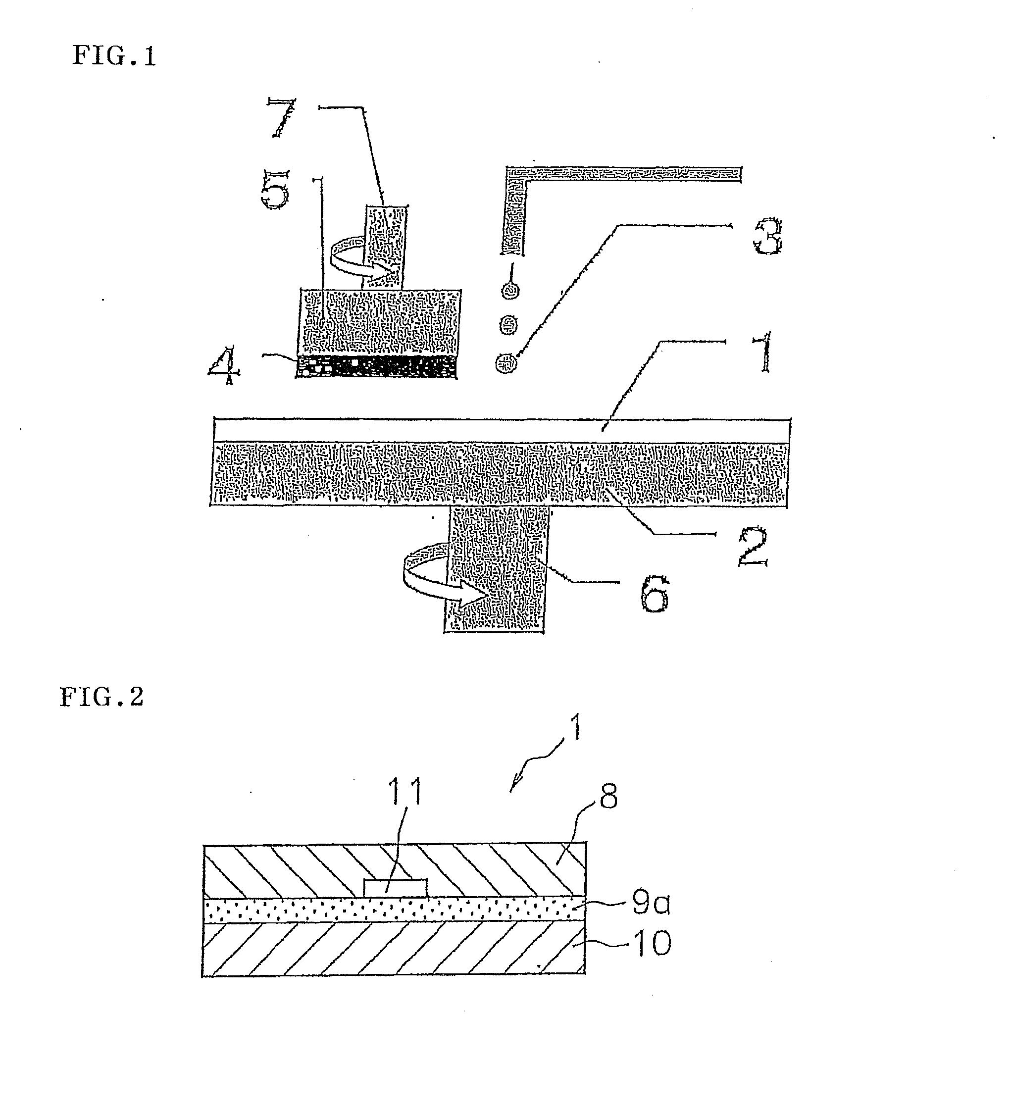
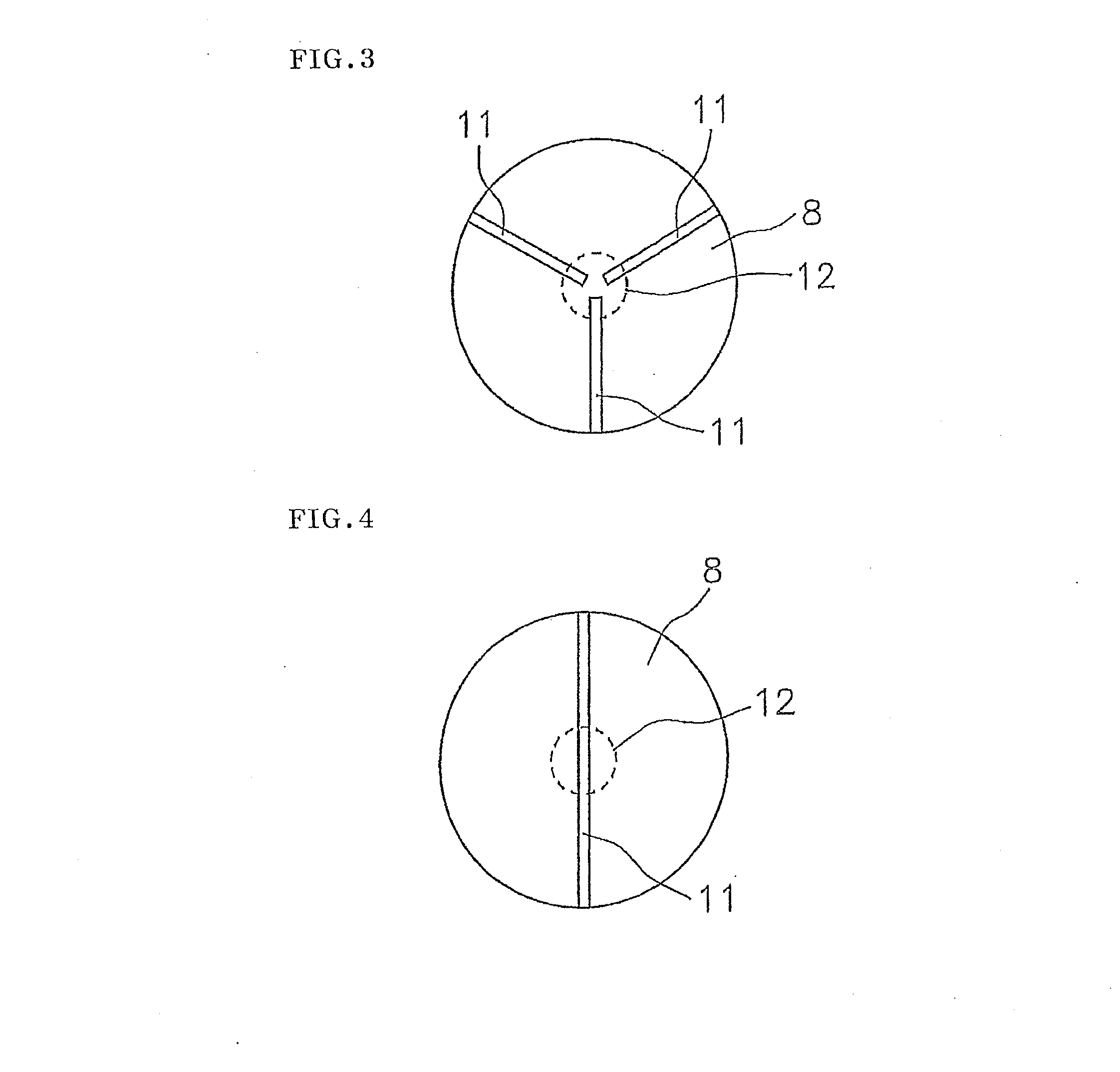
[0120]Using a grooving machine (manufactured by Techno Corporation), grooves with a width of 1.0 mm and a depth of 0.1 mm were radially formed as the non-adhering region X on the back surface of the polishing layer, which was prepared in Production Example 1, at angle intervals of 45° from the center to the peripheral end. The total surface area of the non-adhering region X was 0.84% of the surface area of the polishing layer. Subsequently, a 60-cm diameter double-sided adhesive tape (base film: a 25-μm thick PET film, adhesive layers: 50-μm thick acrylic adhesive layers) was bonded to the back surface of the polishing layer using a laminating machine. A 60-cm diameter cushion layer (a polyurethane foam with a thickness of 0.8 mm) was then bonded to the other side of the double-sided adhesive tape, so that a laminate polishing pad was obtained.

example 2

[0121]Using a grooving machine (manufactured by Techno Corporation), grooves with a width of 1.0 mm and a depth of 0.1 mm were radially formed as the non-adhering region X on the back surface of the polishing layer, which was prepared in Production Example 1, at angle intervals of 45° from the center to the peripheral end. In addition, a concentric groove with a width of 0.25 mm and a depth of 0.1 mm was formed as the non-adhering region X at a position 100 mm apart from the center in the radial direction. The total surface area of the non-adhering region X was 0.91% of the surface area of the polishing layer. Subsequently, a laminate polishing pad was prepared by the same method as in Example 1.


PUM

PropertyMeasurementUnit
Fractionaaaaaaaaaa
Lattice constantaaaaaaaaaa
Surface areaaaaaaaaaaa

Abstract

An object of the invention is to provide a laminate polishing pad having a polishing layer and a cushion layer, which resist peeling. A laminate polishing pad including: a polishing layer with no region passing therethrough; an adhesive member; and a cushion layer placed on the polishing layer with the adhesive member interposed therebetween, wherein the back side of the polishing layer has at least one non-adhering region X continuously extending from a central region of the polishing layer to a peripheral end of the polishing layer, and/or the adhesive member has at least one non-adhering region Y continuously extending from a central region of the adhesive member to a peripheral end of the adhesive member.

Description

REFERENCE TO RELATED APPLICATIONS[0001]This application is a national stage application under 35 USC 371 of International Application No. PCT / JP2011 / 055817, filed Mar. 11, 2011, which claims the priority of Japanese Patent Application No. 2010-070698, filed Mar. 25, 2010, Japanese Patent Application No. 2010-242551, filed Oct. 28, 2010, and Japanese Patent Application No. 2011-044192, filed Mar. 1, 2011, the entire contents of which are incorporated herein by reference.FIELD OF THE INVENTION[0002]The present invention relates to a laminate polishing pad by which the planarizing processing of optical materials such as lenses, reflecting mirrors and the like, silicon wafers, glass substrates for hard disks, aluminum substrates, and materials requiring a high degree of surface planarity such as those in general metal polishing processing can be carried out stably with high polishing efficiency. The laminate polishing pad of the present invention is used particularly preferably in a pro...

Claims


Application Information

Patent Timeline
IPC IPC(8): B24D11/00H01L21/304B24B37/22B24B37/26
CPCB24B37/26B24B37/22B24B37/20B24B37/24H01L21/304
Inventor KAZUNO, ATSUSHI
Owner ROHM & HAAS ELECTRONICS MATERIALS CMP HLDG INC
Why Eureka
Try Eureka