Control device of internal combustion engine

a control device and internal combustion engine technology, applied in the direction of electric control, machines/engines, instruments, etc., can solve the problems of reducing the accuracy of air-fuel ratio control at start-up, affecting the efficiency of air-fuel ratio control, and unable to compute the amount of condensed water with high accuracy, so as to prevent a decrease in fuel efficiency and exhaust performance, the effect of high accuracy

Active Publication Date: 2013-01-24
HITACHI ASTEMO LTD
View PDF5 Cites 21 Cited by
  • Summary
  • Abstract
  • Description
  • Claims
  • Application Information

AI Technical Summary

Benefits of technology

[0009]According to the aspect of the invention, it is possible to compute the mass of condensed water in the exhaust pipe with high accuracy and determine whether or not to perform sensor element heating control of the air-fuel ratio sensor with high accuracy. This makes it possible to prevent a crack in the sensor element of the air-fue

Problems solved by technology

However, after the internal combustion engine is started, a large part of the period in which the condensed water is present in the exhaust pipe is an evaporation process in which the exhaust pipe is above the dew point, and, since transfer of mass and energy between the exhaust gas and the condensed water is an important factor during the evaporation process, it is impossible to compute the amount of condensed water with high accuracy based only on the relative wall temperature a

Method used


Image

  • Control device of internal combustion engine
  • Control device of internal combustion engine
  • Control device of internal combustion engine

Examples


first embodiment

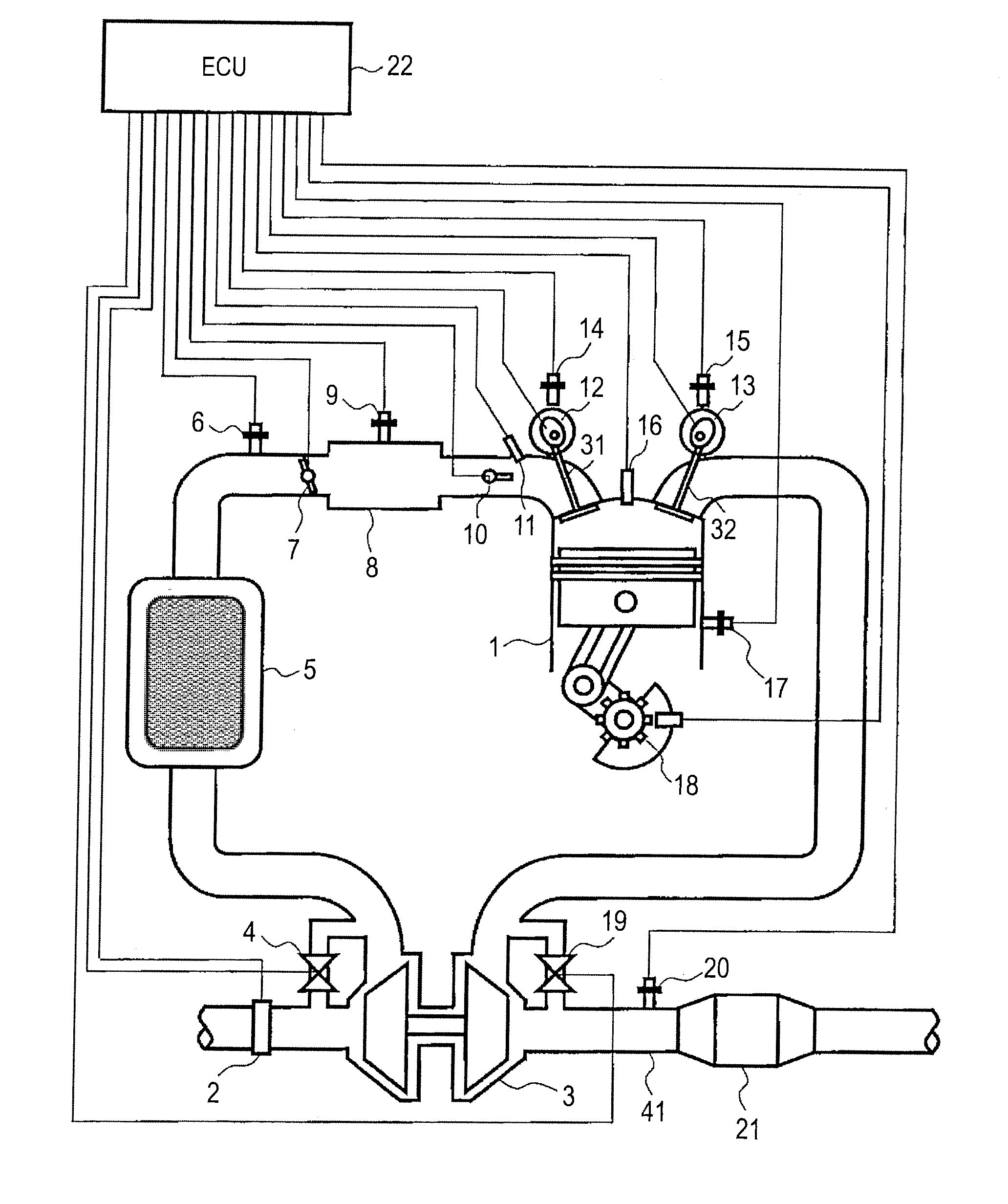
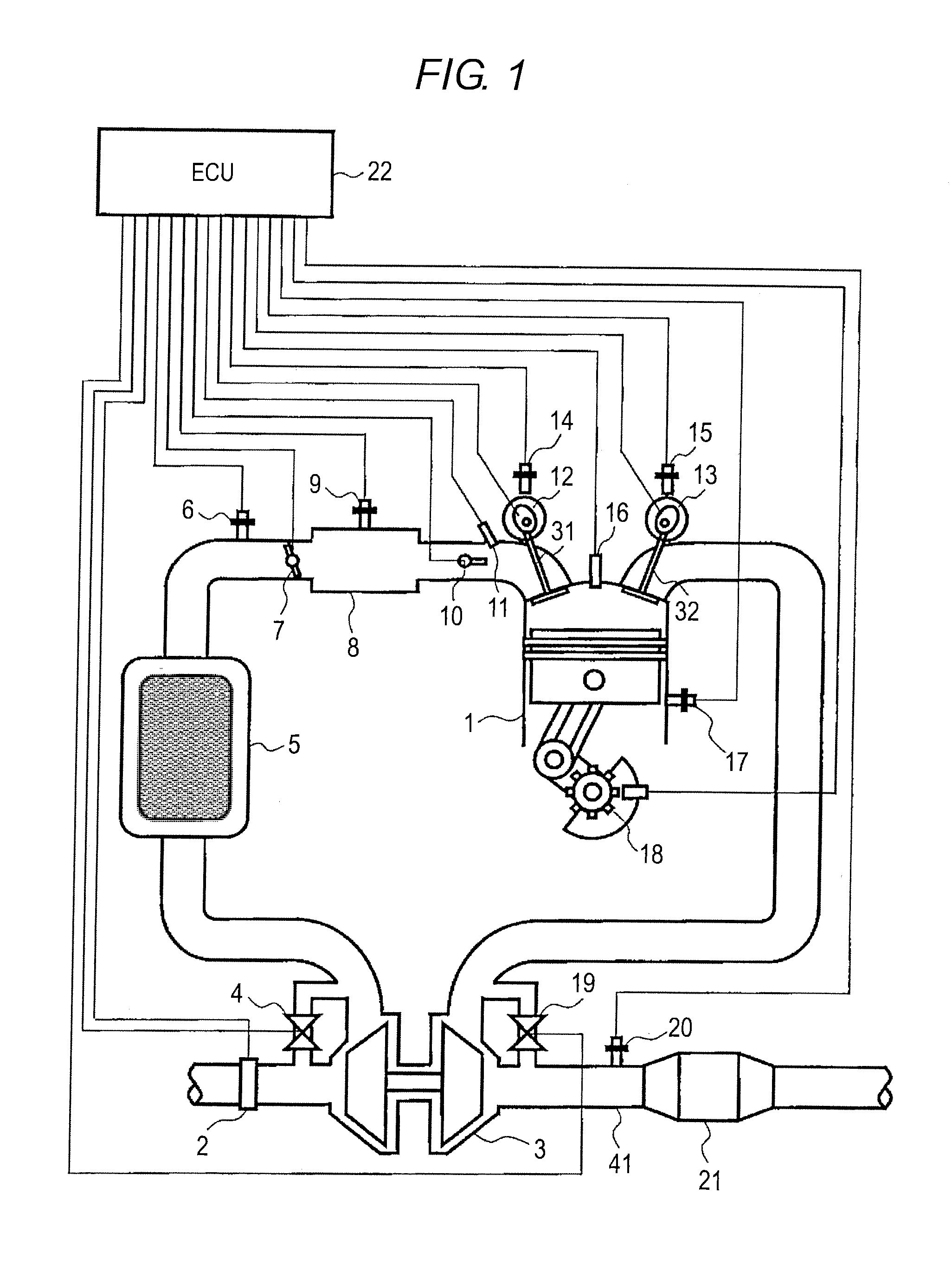
[0033]FIG. 1 is a diagram illustrating an engine system in a structure of a first embodiment. The engine system of this embodiment is an engine system for an automobile and includes an internal combustion engine 1. An intake passage and an exhaust passage communicate with the internal combustion engine 1. To the intake passage, an air flow sensor and an intake air temperature sensor 2 incorporated into the air flow sensor are attached. To the intake passage and the exhaust passage, a turbosupercharger 3 is connected. The turbosupercharger 3 has a compressor connected to the intake passage and a turbine connected to the exhaust passage. The turbosupercharger 3 is formed of the turbine for converting the energy of exhaust gas into rotation of a turbine blade and the compressor for compressing intake air by the rotation of a compressor blade connected to the turbine blade. In a downstream part on that side of the turbosupercharger 3 where the compressor is disposed, an intercooler 5 fo...

second embodiment

[0094]Next, a second embodiment of the invention will be described. The feature of this embodiment is that the mass of condensed water is computed based on the transfer function of condensation and evaporation. It is to be noted that such components as are similar to those of the first embodiment are identified with the same reference numerals and their detailed descriptions will be omitted.

[0095]FIG. 18 is a block diagram showing how to compute the mass of condensed water based on the transfer function. This block diagram indicates the detailed computing processing in step 303 in FIG. 3. In a dew-point computing unit of block 1801, the dew point is computed based on the atmospheric pressure and the exhaust gas water vapor partial pressure. In an exhaust pipe temperature computing unit of block 1802, the exhaust pipe temperature is computed based on the exhaust gas temperature, the exhaust gas mass flow rate, the outside air temperature, the vehicle speed, and the start-up exhaust p...


PUM


Abstract

Control device of an internal combustion engine that determines whether or not to perform sensor element heating control of an air-fuel ratio sensor with high accuracy based on the mass of condensed water in an exhaust pipe. The control device computes the rate of change of condensed water mass in an exhaust pipe based on the saturated water vapor pressure and the water vapor partial pressure of exhaust gas, and computes the rate of change of evaporation mass in the exhaust pipe based on the amount of heat which the condensed water receives in the exhaust pipe. The control device updates the mass of condensed water based on the rate of change of condensed water mass and the rate of change of evaporation mass, and determines whether or not to perform heating control by a heating controlling unit based on the updated mass of condensed water.

Description

BACKGROUND OF THE INVENTION[0001]1. Field of the Invention[0002]The present invention relates to a control device of an internal combustion engine, the control device that determines whether or not to perform sensor element heating control of an air-fuel ratio sensor based on the mass of condensed water that develops in an exhaust pipe.[0003]2. Description of the Related Art[0004]JP-A-2009-228564 discloses the technology to compute the mass of condensed water by map-computing the condensed water integrated quantity based on a relative wall temperature which is a difference between an estimated exhaust pipe temperature and the dew point and an exhaust gas mass flow rate and adding the condensed water integrated quantity to a previous value in a control device of an exhaust gas sensor, the control device that controls the energization state of a heater that heats the exhaust gas sensor provided in an exhaust pipe of an internal combustion engine. The condensed water integrated quantit...

Claims


Application Information

Patent Timeline
IPC IPC(8): F02D41/26F02D43/04
CPCF02D2041/1472F02D41/062F02D2041/1433F02D41/1446F02D41/1494F02D41/1445
Inventor SUZUKI, KUNIHIKOHORI, TOSHIOMATSUFUJI, KOJITAKADA, KENJIKAMOSHITA, HEIKICHISEKINE, HIROSHI
Owner HITACHI ASTEMO LTD
Why Eureka
Try Eureka