Hydrogen and Nitrogen Recovery from Ammonia Purge Gas

Inactive Publication Date: 2013-02-14
CASALE SA
View PDF4 Cites 20 Cited by
  • Summary
  • Abstract
  • Description
  • Claims
  • Application Information

AI Technical Summary

Benefits of technology

[0028]The notable advantage of the invention is that a recovered hydrogen and nitrogen are made available at a pressure substantially equal to the pressure of the feed stream of the recovery unit, which means at a pressure close to the loop pressure. For example, preferred embodiments of the invention provide that hydrogen and nitrogen are recovered at a pressure which is 90% or more of loop pressure.
[0029]Hydrogen and nitrogen recovered at such high pressure can be reintroduced directly into the loop. Preferably the recovery unit according to the invention can be connected on the suction of the circulator, more precisely the purge stream can be taken at a point downstream the synthesis converter section and the recovery unit placed in parallel with the cold exchangers in the synthesis loop, with the recovered stream returned to the suction of the circulator, so that the power requirement of the syngas compressor is not impacted in any way. As an alternative, it can be connected across the circulator of the loop: the purge gas is taken at the delivery side of the circulator, upstream the synthesis converter section, and the gaseous stream containing recovered hydrogen and nitrogen is re-introduced into the synthesis loop at the suction side of said circulator, meaning that the pressure lost in the recovery unit substantially equals the pressure difference across the circulator. This pressure difference is typically around 3 to 10 bar, depending on the selected extraction point.
[0030]If appropriate, a small compressor can be arran

Problems solved by technology

A drawback of membrane-based systems however is that the hydrogen-rich gas is made available at a pressure much lower than that of the synthesis loop.
This means that the load and energy consumption of the compressor are increased or, in oth

Method used


Image

  • Hydrogen and Nitrogen Recovery from Ammonia Purge Gas
  • Hydrogen and Nitrogen Recovery from Ammonia Purge Gas
  • Hydrogen and Nitrogen Recovery from Ammonia Purge Gas

Examples


Embodiment Construction

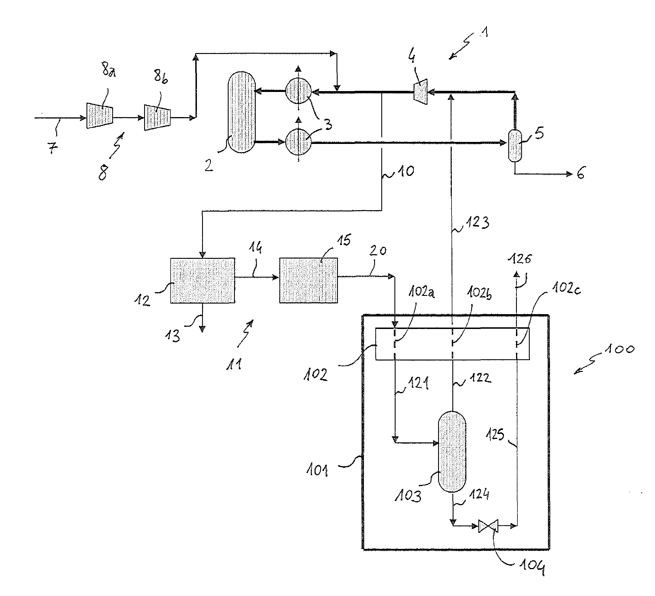
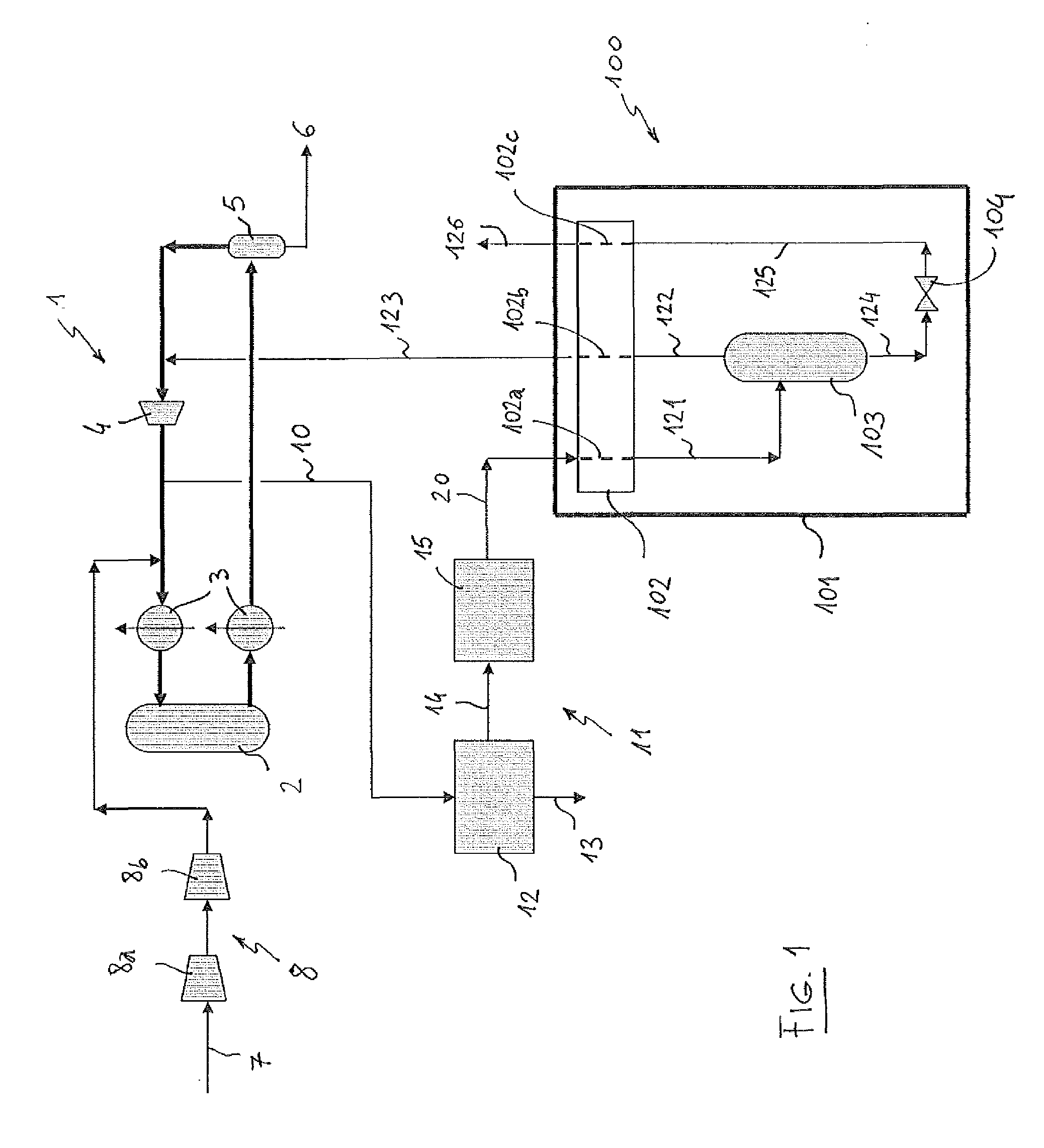
[0051]Referring to the first embodiment of FIG. 1, a plant for synthesis of ammonia from a make up gas containing hydrogen and nitrogen comprises a synthesis loop 1 operating at a loop pressure, which is usually a high pressure such as 150 bar or more. The loop 1 comprises basically a converter 2, heat exchangers 3, a circulator 4 and a separator 5, delivering the ammonia product 6. The loop is fed with make-up gas 7 by means of a main compression unit 8.

[0052]The make-up gas 7 is produced in a front-end section of the plant, for example by reforming a suitable hydrocarbon source, at a pressure significantly lower than the loop pressure of loop 1. The main compression unit 8 raises the pressure of the make up gas delivered by said front-end section to the pressure level of the loop. The compression unit 8 is normally a multi-stage unit, in the figure two stages 8a and 8b are shown. The circulator 4 overcomes the pressure losses along the loop 1 itself, including the pressure losses ...


PUM


Abstract

An ammonia plant is disclosed, where ammonia purge gas (20), is sent to a cryogenic recovery unit, said recovery unit comprising means of cooling (102, 202, 302, 402, 502) and a high-pressure phase separator (103, 203, 303, 403, 503) operating at loop pressure; inside said unit the purge gas (20) is cooled to a cryogenic temperature, and a partial liquefaction of methane and argon is achieved; the high-pressure phase separator separates the cooled stream into a gaseous stream and a bottom liquid; the gaseous stream is reheated in a passage of a heat exchanger; the unit is then capable to export a gaseous stream (123, 223, 323, 423, 523) containing nitrogen and hydrogen at loop pressure, that can be reintroduced at the suction side of the circulator (4) of the loop.

Description

FIELD OF THE INVENTION[0001]The invention relates to the field of synthesis of ammonia from a make-up gas containing hydrogen and nitrogen. More in detail, the invention discloses a novel process and unit for recovery of hydrogen and nitrogen, and optionally of argon, from the purge gas which is taken from the high-pressure synthesis loop of an ammonia plant.PRIOR ART[0002]A known process to produce ammonia involves the catalytic reaction of a make-up synthesis gas comprising hydrogen (H2) and nitrogen (N2), in a high-pressure (HP) synthesis loop usually operating at around 80-300 bar pressure. The make-up syngas is produced in a front-end section, upstream the synthesis loop, by reforming a suitable hydrocarbon feed such as natural gas. For example, the hydrocarbon feed is desulphurized, then steam-reformed in a primary reformer, obtaining a first gas product containing CO, CO2 and H2 at a temperature around 800° C.; the first gas product is further reacted with air, enriched air o...

Claims


Application Information

Patent Timeline
IPC IPC(8): C01C1/04
CPCC01B3/025C01B3/506C01B3/52C01B3/56C01C1/0476C01B2203/0465C01B2203/048C01B2210/007C01B2210/0082C01B2203/0415Y02P20/52F25J3/062F25J3/068F25J3/0219F25J3/0233F25J3/0276F25J3/0285F25J2200/80F25J2205/04F25J2210/20F25J2245/02F25J2270/02F25J2200/74F25J2240/30F25J2215/02F25J2230/30F25J2270/12F25J2270/42C01C1/04
Inventor OSTUNI, RAFFAELEFILIPPI, ERMANNOSKINNER, GEOFFREY FREDERICK
Owner CASALE SA
Why Eureka
Try Eureka