Method of making cohesive carbon assembly and its applications

a carbon and carbon technology, applied in the preparation of carboxylic compounds, cell components, transportation and packaging, etc., can solve the problems of anisotropic and largely unidirectional properties of the assembly, adversely affecting the electrical properties of the structure, and limited to the scale of the starting cnt fores

Active Publication Date: 2013-02-14
YAZAKI CORP
View PDF6 Cites 46 Cited by
  • Summary
  • Abstract
  • Description
  • Claims
  • Application Information

AI Technical Summary

Problems solved by technology
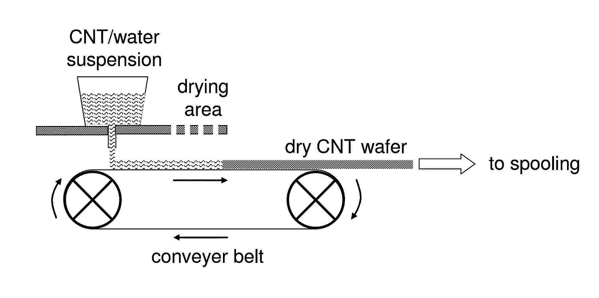
Furthermore, the self-assembled structures disclosed therein comprise functional agents to bond the CNTs together, which may adversely affect the structures' electrical properties.
These methods involve a sequence of solvent washing, pressing, and / or drying steps and are limited to the scale of the starting CNT forest.
Furthermore, these assemblies are characterized by a predominant orientation or alignment of the CNTs, which imparts the assembly with anisotropic and largely unidirectional properties.
Also, the CNTs are not uniformly distributed within the assemblies, and the assemblies have large macropores and very high porosity (>80%).
These assemblies, however, show low bulk density of 0.45 g / cm3 or less (0.1 g / cm3 in the case of SWCNT), requiring an impractically high volume of material for adequate capacitor performance.
Scalability of these CNT forests for manufacturing purposes is questionable, and they have inferior mechanical properties for use as current collectors.
This assembly has similar drawbacks as that of Signorelli; namely, low density, non-scalability, and inferior mechanical properties.
However, a sealed capacitor device could not be produced using this assembly due to excessive swelling when impregnated with the liquid electrolyte, indicating that the assembly had inferior mechanical strength and integrity.
However, bromine is corrosive, highly toxic, environmentally harmful, and expensive.

Method used


Image

  • Method of making cohesive carbon assembly and its applications
  • Method of making cohesive carbon assembly and its applications
  • Method of making cohesive carbon assembly and its applications

Examples


example 1

Fabrication of Free Standing CNT Wafer from Aqueous Dispersion Using Sonication and Microfluidization

Preparation of Aqueous CNT Dispersion

[0117]As-received amide-functionalized SWCNT (P9 SWNT, CSI Inc., Riverside, Calif.) was ground by mortar and pestle. Three masses of the ground material, 240 mg, 200 mg, and 160 mg, were separately combined with 40 g each of de-ionized (DI) water in a beaker, to create CNT / water dispersions with ratios (mg / g) of 6:1, 5:1, and 4:1 respectively. To facilitate dispersion of the CNT loadings in water, each mixture was sonicated for 2 cycles of 10 minute duration (total 20 minutes) using a probe sonicator (V600, Sonics & Materials, Inc., Newtown, Conn.). The probe tip was directly immersed into the CNT / water mixture for sonication. The suspension became black after 10 seconds of sonication.

[0118]Immediately after sonicating, the resulting CNT / water dispersions were passed once through a microfluidizer (M-110Y, Microfluidics Corporation, Newton, Mass.),...

example 2

Fabrication of Free Standing CNT Wafer from Aqueous Dispersion Using Refluxing and Microfluidization

Preparation of Aqueous CNT Dispersion

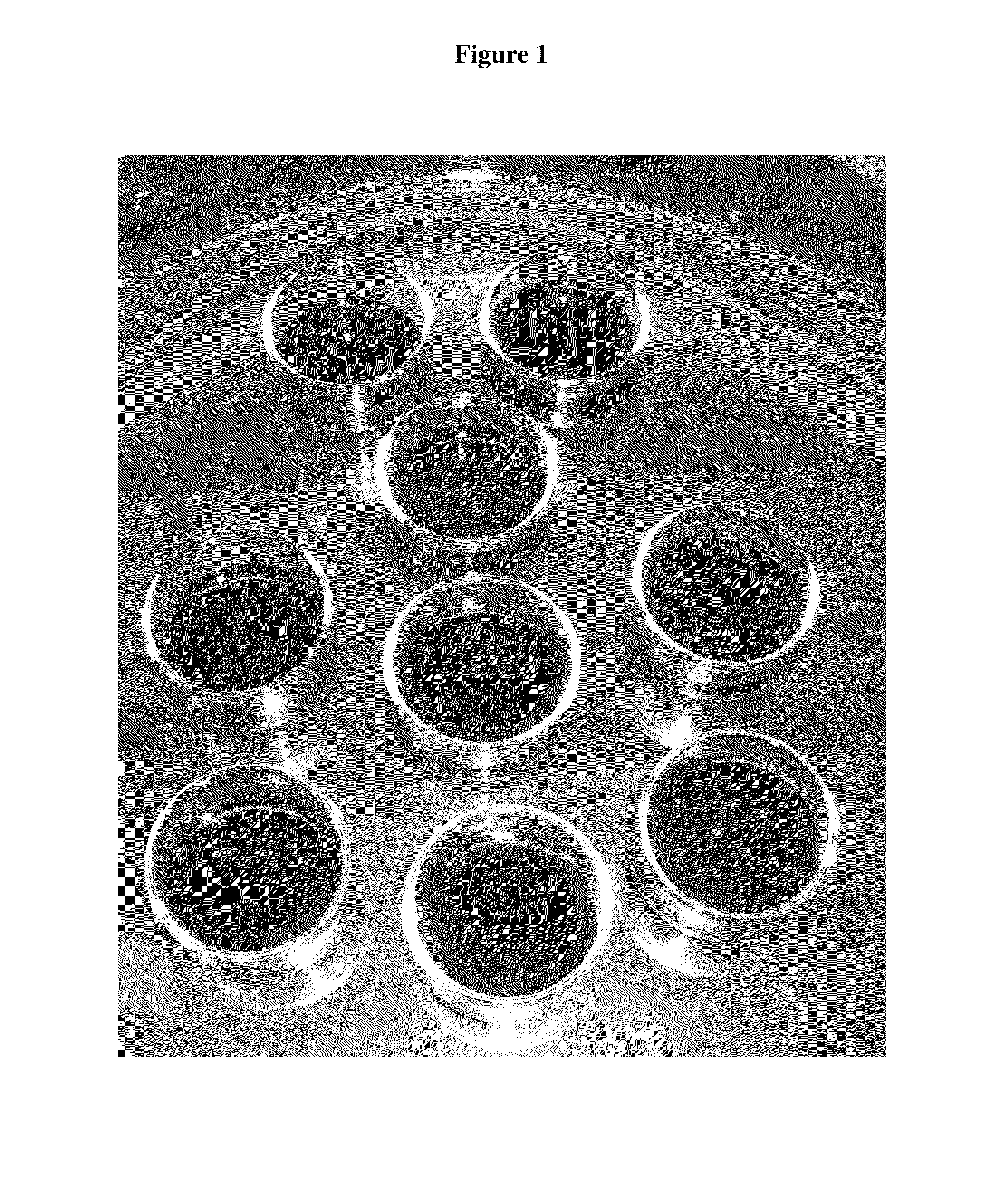
[0123]Approximately 400 mg of carboxyl-functionalized SWCNT (P3 SWNT, CSI Inc.) were combined with 80 mL of DI water in a round bottom flask to create a CNT / water dispersion with ratio of 5:1 (mg / g). The CNT / water mixture was refluxed in boiling water while stiffing for 4 hours. The resulting dispersion was divided into two 40-mL portions, and each of these was passed through the microfluidizer one time. For each 40 mL portion, the primary and three residual dispersions (R1-R3) were collected as the effluent streams by flushing with DI water as described in Example 1. CNT concentrations in the residual dispersions were determined by casting fixed volumes of each into dishes and then weighing the resulting assemblies after completely evaporating the water. The CNT concentrations of dispersions R1, R2, and R3 were determined to be 2.0, 0.8, and 0.4 m...

example 3

Fabrication of Adherent CNT Assemblies on Aluminum Substrates

[0126]Aqueous CNT (CSI Inc. P3 SWNT) dispersions were prepared via the sonication-microfluidization route (Example 1) and the refluxing-microfluidization route (Example 2).

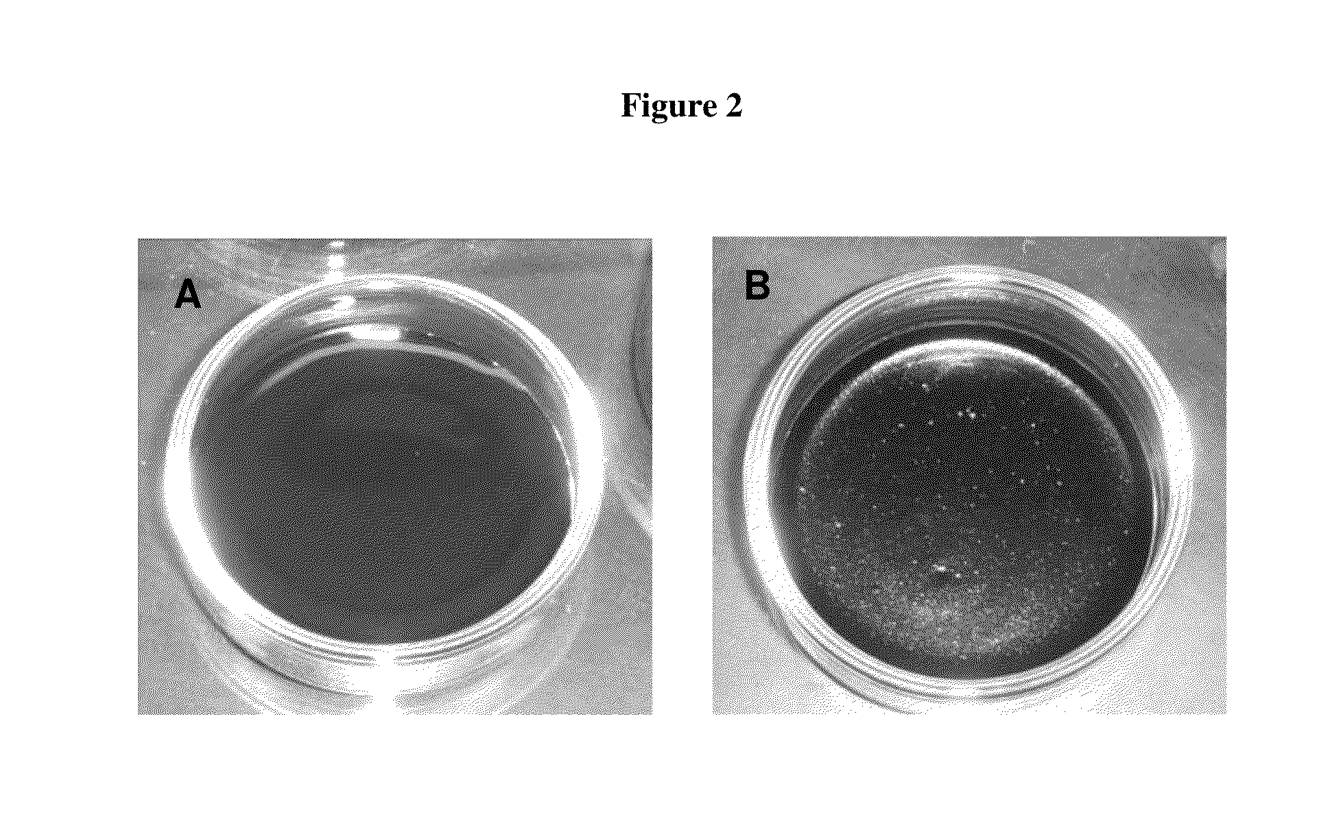
[0127]For the aqueous CNT dispersion prepared according to Example 1, residual dispersions R1, R2, and R3 were collected after microfluidization, as described in Example 2. About 5 ml of the first (R1) residual dispersion were cast directly into an aluminum foil pan 4 cm in diameter, which had been etched with dilute NaOH solution for 2 minutes to promote adhesion of the CNT assembly. The etched Al pan was lined along its inside periphery with tape to expose only the base for CNT contact and adhesion. To another similarly treated Al pan, 5 mL of R2 CNT / water dispersion were cast. Water was allowed to evaporate from the cast dispersions under ambient conditions of temperature and pressure. Evaporation completed in about three days.

[0128]For the aqueous CN...


PUM

PropertyMeasurementUnit
electrical sheet resistanceaaaaaaaaaa
porosityaaaaaaaaaa
densityaaaaaaaaaa

Abstract

Cohesive carbon assemblies are prepared by obtaining a functionalized carbon starting material in the form of powder, particles, flakes, loose agglomerates, aqueous wet cake, or aqueous slurry, dispersing the carbon in water by mechanical agitation and/or refluxing, and substantially removing the water, typically by evaporation, whereby the cohesive assembly of carbon is formed. The method is suitable for preparing free-standing, monolithic assemblies of carbon nanotubes in the form of films, wafers, discs, fiber, or wire, having high carbon packing density and low electrical resistivity. The method is also suitable for preparing substrates coated with an adherent cohesive carbon assembly. The assemblies have various potential applications, such as electrodes or current collectors in electrochemical capacitors, fuel cells, and batteries, or as transparent conductors, conductive inks, pastes, and coatings.

Description

[0001]This application claims priority to U.S. Provisional Application No. 61 / 523,125, filed Aug. 12, 2011; the content of which is incorporated herein by reference in its entirety.TECHNICAL FIELD[0002]This invention relates to a cohesive assembly of carbon, and to methods for preparing a cohesive assembly of carbon, in which the starting carbon materials, under certain prescribed conditions, self-assemble into a disc, wafer, film, fiber, wire, or other object of a desired shape. In preferred embodiments, the carbon assembly prepared by the invented method comprises carbon nanotubes. The prepared assembly shows good mechanical strength and integrity, high carbon packing density, high surface area, and low electrical resistivity, and has various potential applications such as in electrical power storage and conductive coatings and films. The cohesive assembly of carbon is especially useful as an electrode or a current collector for an electrochemical capacitor, fuel cell, or battery....

Claims


Application Information

Patent Timeline
Patent Type & Authority Applications(United States)
IPC IPC(8): C07C51/00C07C231/00C07C233/64B05D5/12H01M4/64H01G9/042C07C63/33B82Y30/00B82Y40/00B82Y99/00
CPCH01M4/0402H01M4/583H01M4/663H01M4/8825H01M4/8875B82Y40/00H01G11/32Y02E60/50Y02E60/13B82Y30/00H01M4/96C01B32/166Y02E60/10Y10T428/26C01B32/174C01B2202/02C01B2202/22C07C69/00C07C233/00H01M4/64H01M4/8807
Inventor GRIGORIAN, LEONIDBRAHIM, SEAN IMTIAZ
Owner YAZAKI CORP
Why Eureka
Try Eureka