

Membrane-electrode-assembly and fuel cell
a technology of membrane-electrode assembly and fuel cell, which is applied in the manufacture of cell components, final product manufacturing, electrochemical generators, etc., can solve the problems of electrode-assembly to further lower the internal resistance of the entire membrane-electrode assembly, increase the ion conduction resistance of the catalyst electrode layer, etc., and achieves improved resistance to dissolving of catalyst metal in the anode and the cathode. , the effect of low
- Summary
- Abstract
- Description
- Claims
- Application Information
AI Technical Summary
Benefits of technology
Problems solved by technology
Method used
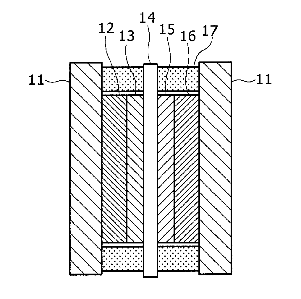
Image

Examples
example 2
Manufacture of Example 2
[0119](7-1) A Pd / C catalyst and the solution product of the polymer C prepared in (5-1) were mixed in a solvent including ethylene glycol monomethyl ether as a main ingredient. The Pd / C catalyst and the polymer C were at a dry weight ratio of 1:0.09. They were stirred for 12 hours by a magnetic stirrer to prepare a Pd / C slurry for a cathode in which the Pd / C catalyst and the polymer having trimethyl amino groups were present in admixture. This is hereinafter referred to as a slurry G.
(7-2) The slurry G obtained in (7-1) was dried while evaporating the solvent using a spray drier to obtain a powder. The powder was pulverized and sieved. Then, the product was washed with 0.1M aqueous KOH and rinsed with pure water and dried. This is referred to as a powder G. As a preliminary investigation, when the powder G was immersed in an aqueous propanol solution and stirred by a magnetic stirrer, the polymer was not leached from the powder.
(7-3) After adding the powder G...
example 3
Manufacture of Example 3
[0120](8-1) The slurry G obtained in (7-1) was coated on a 50 mm×50 mm PTFE sheet by using a spray coater. After drying, it was dipped in an aqueous solution of 0.1M KOH, washed with water, and dried to form a cathode.
(8-2) A diluted Nafion dispersion was coated over the cathode obtained in (8-1), impregnated into the cathode, dried, then rinsed with pure water, and dried again. In this process, the Pd / C catalyst, the polymer C, and the Nafion in the electrode were at a mixing ratio of 1:0.09:0.09 by dry weight.
(8-3) The slurry A was coated on one surface of the electrolyte membrane A by using a spray coater to form an anode. After washing the electrolyte membrane attached with the anode with an aqueous solution of 1M sulfuric acid, it was subjected to a rinsing treatment with super purified water and dried. The cathode and the electrolyte membrane were joined by bonding the cathode-coated PTFE sheet obtained in (8-2) to the back of the electrolyte membrane a...
example 4
Manufacture of Example 4
[0121](9-1) A membrane-electrode-assembly was prepared in the same manner as in Example 2 except for changing the solution product of the polymer to be mixed with the Pd / C catalyst to the solution product of the polymer B in (7-1).
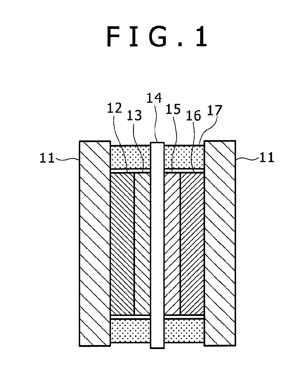
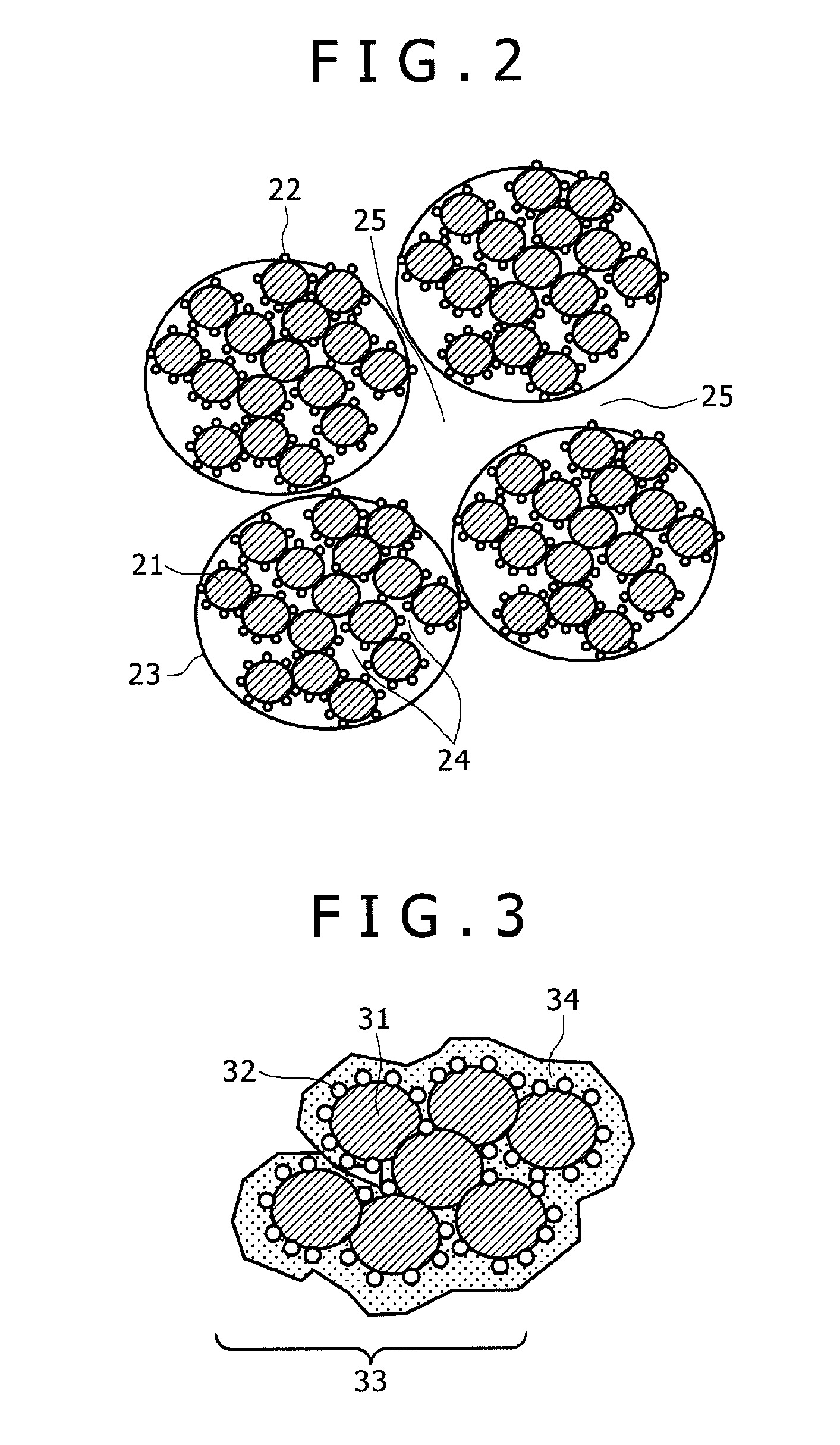
(9-2) When the cathode of the membrane-electrode-assembly obtained in (9-1) was sliced by a freezing microtome and observed by STEM-EDX, presence of an F-containing resin (Nafion (R)) was confirmed at the periphery of the Pd / C agglomerate covered with an N-containing resin (polymer C).
PUM
| Property | Measurement | Unit |
|---|---|---|
| pKa | aaaaa | aaaaa |
| aspect ratio | aaaaa | aaaaa |
| particle diameter | aaaaa | aaaaa |
Abstract
Description
Claims
Application Information