Fully integrated thermoelectric devices and their application to aerospace de-icing systems

a fully integrated, thermoelectric module technology, applied in the manufacture/treatment of thermoelectric devices, lighting and heating apparatus, machine operation modes, etc., can solve the problems of limited prior art embodiments to niche applications, limited thermoelectric efficiencies, and high cost, so as to improve thermoelectric efficiencies, improve efficiency, and reduce the effect of thermal load

Active Publication Date: 2013-03-14
DE ROCHEMONT L PIERRE
View PDF0 Cites 34 Cited by
  • Summary
  • Abstract
  • Description
  • Claims
  • Application Information

AI Technical Summary

Benefits of technology

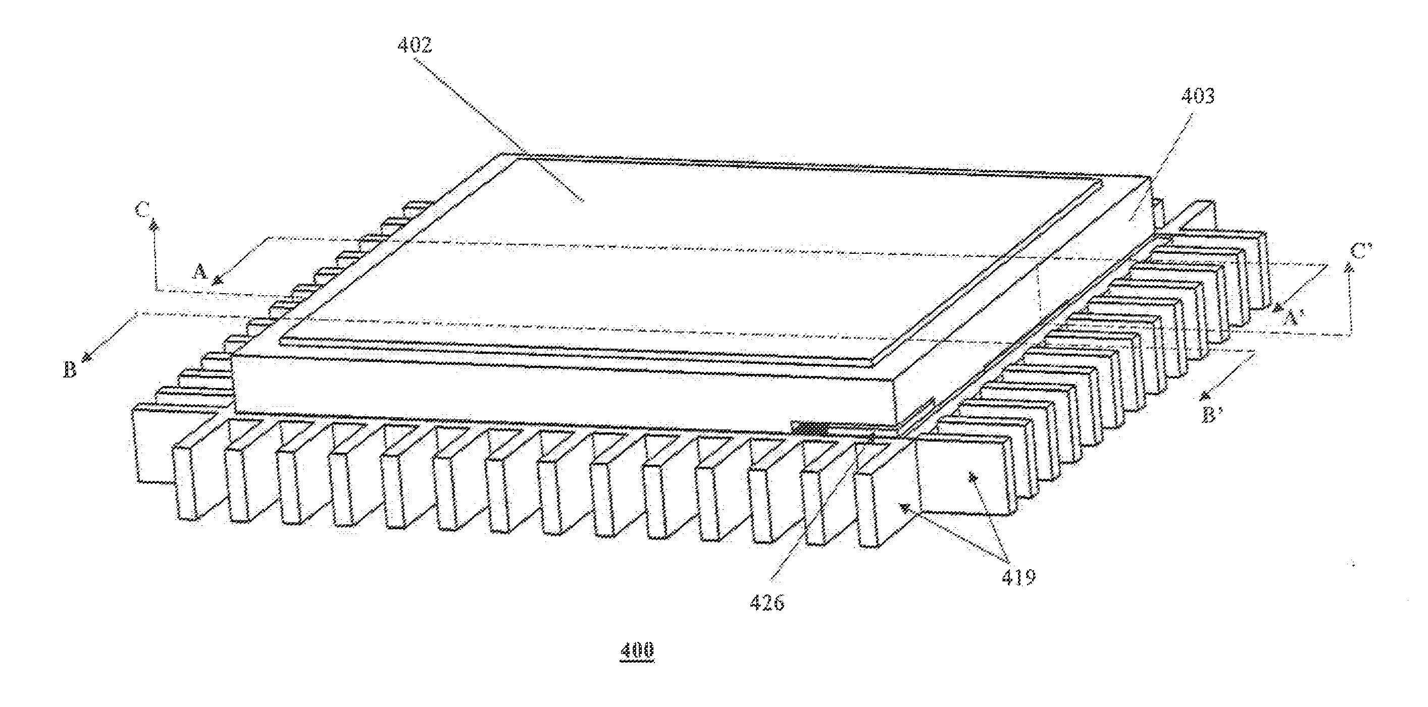
[0066]The present invention relates generally to the complete integration of all electrical elements needed to form a thermoelectric circuit into a fully integrated solid state Peltier module. More specifically, the present invention instructs methods and means to form semiconducting circuit elements that are endowed with a nanoscale polycrystalline microstructure that is chemically uniform at the atomic scale to enhance thermoelectric efficiencies of the fully integrated thermoelectric device. In particular, the invention teaches the use of one or more of these enhanced efficiency solid state modules to redistribute thermal loads within an aircraft or on at least one of its aerodynamic surfaces. In one instance, the invention establishes means to improve the figure of merit of Peltier modules through superior polycrystalline microstructures. In another instance, the invention provides means to fully integrate a thermoelectric system into a solid state device. In yet another instance, the invention provides means to de-ice the aerodynamic surfaces of an aircraft through the direct construction of the fully integrated Peltier module(s) on said aerodynamic surface or by first forming a pliable tape structure that can he laminated onto the aerodynamic surfaces using an adhesive agent. In a further instance, the invention provides means to convert heat to electricity, wherein said heat is collected on hot surfaces of an aircraft or flight system, and to use said electricity to power other systems, including the generation of heat in locations of the flight system where it is desired.

Problems solved by technology

However, the efficiencies of TE systems remain well below that of their mechanical counterparts and their high cost often limits prior art embodiments to niche applications.
As discussed below, the limitations are due primarily to the methods used to manufacture thermoelectric systems.
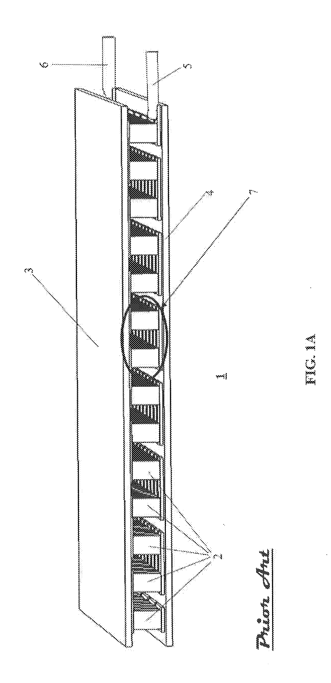
The discrete assembly process is a principal drawback to modern TE systems, Discrete assemblies require semiconductor elements to be individually prepared (manufactured, finished, and in some instances tested) prior to qualifying for final assembly.
Manufacturing methods that involve a large number of steps do not lend themselves to low cost production, nor are they suitable in very small scale microfluidic systems.
These systems are restricted in their commercial utility either through the higher cost of stacking lower efficiency modules and / or the limited applications realm of thin films devices where thermopower quotients are geometrically limited by the thickness of the thin films.
The leading cause for their high cost is the discrete assembly of the module components.
These discrete assemblies include costs associated with semiconductor crystal growth, which can take weeks, ingot slicing, wafer dicing and element polishing, in addition to the discrete assembly process itself, which add cumulative labor and supply chain management costs to the module's construction.
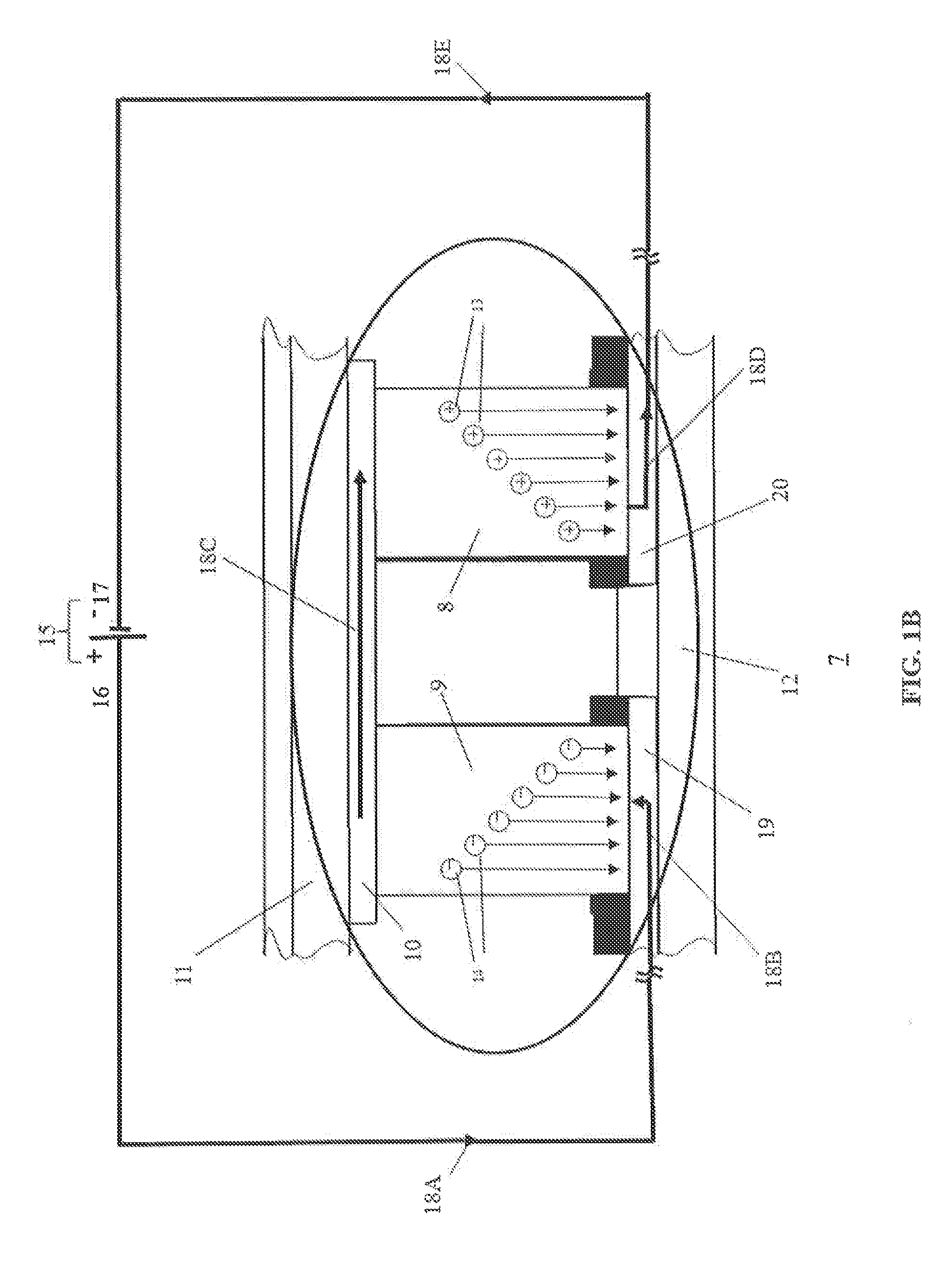
The primary challenge to this phenomenon is that charge carriers (electrons and holes) that conduct electrical currents also convey thermal currents.
These nanoscale irregularities either facilitate electron transport through the semiconductor in some way, or impede thermal conduction through the semiconductor element.
Heterojunction defects can also occur in bulk alloys wherein a chemical non-uniformity in a highly localized region produces a semiconducting compound within micro-volume that is chemically distinct from the hulk material.
While QDSL 47 structures have been useful in mapping a path towards higher thermopower materials, they have limited widespread commercial value due to their geometric limitations and have lower Seebeck coefficients than pure superlattice systems.
Diluting PbTe with indium (In) induces energy sub-bands that fall within the energy gap at room temperature, making In—PbTe alloys unsuitable for many applications.
Diluting PbTe with thallium (Tl) has produced sub-bands that are favorably located for p-type Tl—PbTe diluted alloys, validating the physics articulated in equations 4b & 5b, but it has not been possible to fabricate n-type bulk materials with favorable distortions in their density of states that are needed to complete the thermoelectric circuit.
Aircraft de-icing systems is a particular application in which thermoelectric de-icing systems could have significant value, but to date a means to meet the necessary requirements for efficiency, mechanical flexibility, and temperature differential have not been developed.
Ice accumulation on an aerodynamic surface during flight or while on the ground can alter air foil configuration or add excessive weight that leads to dangerous flying conditions, particularly for general aviation aircraft.
Current de-icing methods pose an environmental hazard as chemical sprays leach into ground water systems.
Electrical de-icing systems are deployed on the larger air frames, but their efficiency not sufficient to eliminate chemical de-icing prior to take-off, so they only assist in the de-icing process.
However, discretely assembled Peltier modules are wholly unsuited for application as aircraft de-icing systems due to both the fragility of the mechanical assembly and their high cost, among numerous other reasons.

Method used


Image

  • Fully integrated thermoelectric devices and their application to aerospace de-icing systems
  • Fully integrated thermoelectric devices and their application to aerospace de-icing systems
  • Fully integrated thermoelectric devices and their application to aerospace de-icing systems

Examples


Embodiment Construction

[0097]This application incorporates by reference all matter contained in de Rochemont and Farmer, “METAL-CERAMIC COMPOSITES WITH IMPROVED INTERFACIAL PROPERTIES AND METHODS TO MAKE SUCH COMPOSITES”, U.S. Pat No. 5,866,252 (the '252 application), de Rochemont and Farmer, “CERAMIC COMPOSITES WITH IMPROVED INTERFACIAL PROPERTIES AND METHODS TO MAKE SUCH COMPOSITES”, U.S. Pat. No. 6,143,432 (the '432 application), de Rochemont and Farmer, “Ceramic Composite Wiring, Structures for Semiconductor Devices and Method of Manufacture”, U.S. Pat. No. 6,323,549 B1, (the '549 application), de Rochemont U.S. Pat. No. 7,405,698 entitled “CERAMIC ANTENNA MODULE AND METHODS OF MANUFACTURE THEREOF” (the '698 application), de Rochemont U.S. Pat. No. 8,178,457 B2 entitled “CERAMIC ANTENNA MODULE AND METHODS OF MANUFACTURE”, (the '457 application, de Rochemont U.S. Ser. No. 11 / 479,159, filed Jun. 30, 2006, entitled “ELECTRICAL COMPONENT AND METHOD OF MANUFACTURE” (the '159 application), U.S. Ser. No. 11 / ...


PUM


Abstract

A thermoelectric module and methods for making and applying same provide an integrated, layered structure comprising first and second, thermally conductive, surface volumes, each in thermal communication with a separate respective first and second electrically conductive patterned trace layers, and an array of n-type and p-type semiconducting elements embedded in amorphous silica dielectric and electrically connected between the first and second patterned trace layers forming a thermoelectric circuit.

Description

CROSS REFERENCE TO RELATED APPLICATIONS[0001]This application claims priority from U.S. Provisional Patent Application Ser. No. 61 / 592,302, filed Aug. 31, 2011, titled FULLY INTEGRATED THERMOELECTRIC DEVICES AND THEIR APPLICATION TO AEROSPACE DE-ICING SYSTEMS, and incorporated herein by reference in its entirety.FIELD OF THE INVENTION[0002]The present invention relates generally to the construction of a fully integrated thermoelectric module and to its various applications including but not limited to the application of a fully integrated thermoelectric module to de-icing aerodynamic surfaces and other systems on board aircraft or space vehicles.BACKGROUND OF THE INVENTION[0003]1. Background on Thermoelectric Systems[0004]Temperature control is integral to the proper functioning of many modern systems and technologies. Mechanical heat pumps, comprising mechanically actuated expansion and compression chambers, are the most efficient heat transfer systems available today. However, the...

Claims


Application Information

Patent Timeline
Patent Type & Authority Applications(United States)
IPC IPC(8): F25B21/02H01L35/34
CPCF25B21/02H01L35/34H01L35/32H01L35/18H01L35/30B64D15/12H10N10/81H10N10/852H10N10/853H10N10/855H10N10/13H10N10/17
Inventor DE ROCHEMONT
Owner DE ROCHEMONT L PIERRE
Why Eureka
Try Eureka