Multi-layered heat transfer tube, manufacturing method of multi-layered heat transfer tube, and forming device used in the manufacturing method
a technology of multi-layered heat transfer and manufacturing method, which is applied in indirect heat exchangers, drawing dies, lighting and heating apparatus, etc., can solve the problems of difficult to significantly improve eating-away resistance, and achieve the effect of improving eating-away resistance against seawater
- Summary
- Abstract
- Description
- Claims
- Application Information
AI Technical Summary
Benefits of technology
Problems solved by technology
Method used
Image
Examples
first embodiment
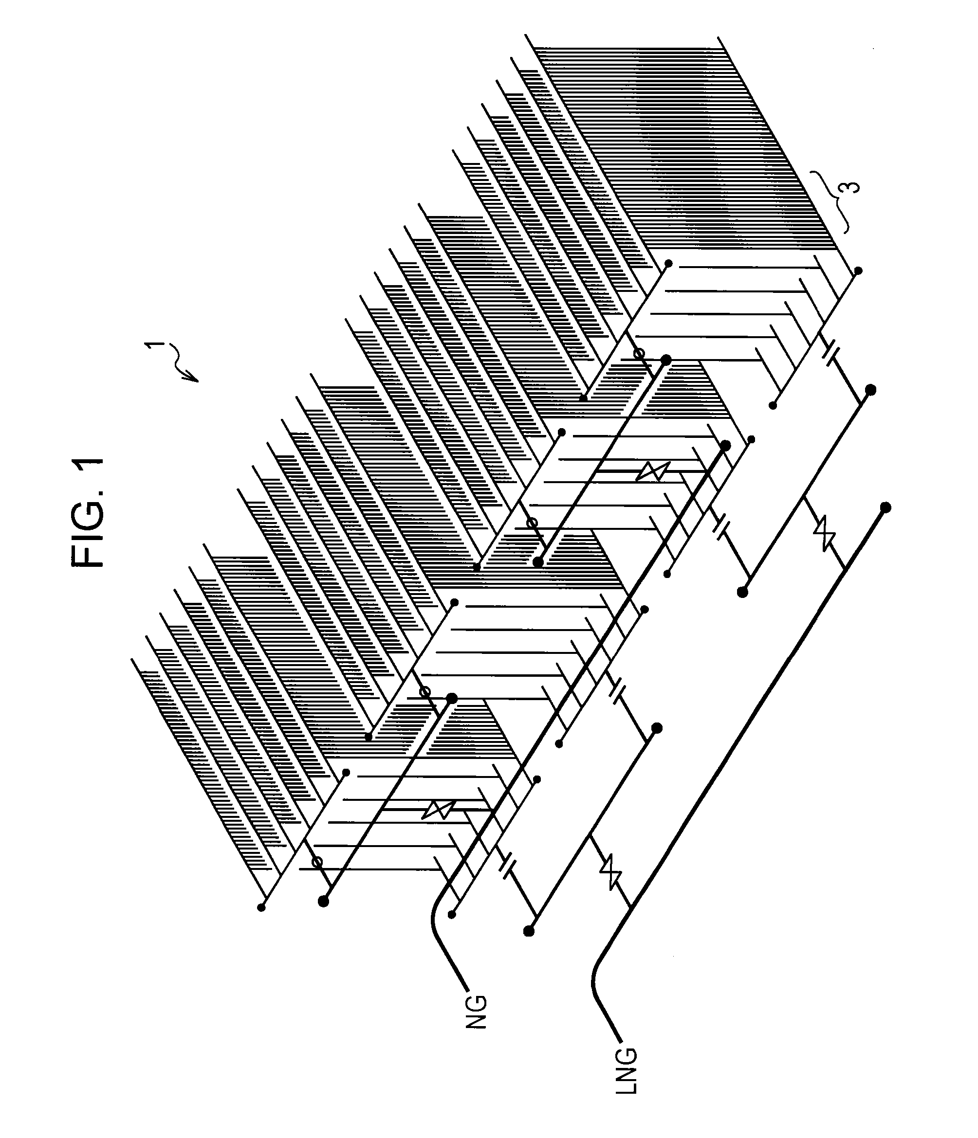
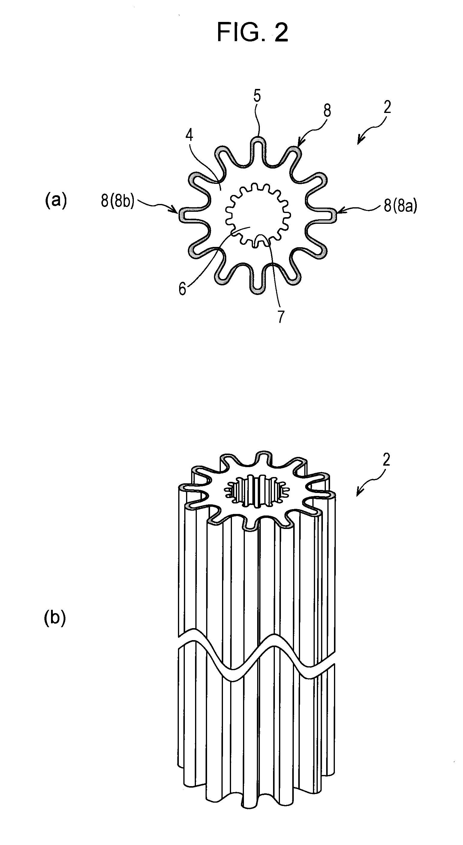
[0019]A multi-layered heat transfer tube according to a first embodiment of the present invention will be described with reference to FIG. 1 and FIG. 2. FIG. 1 is a perspective view schematically showing an open rack vaporizer (ORV) that vaporizes liquefied natural gas (LNG). FIG. 2 (a) and FIG. 2 (b) are diagrams showing the configuration of a multi-layered heat transfer tube in the ORV.
[0020]The ORV 1 shown in FIG. 1 is a kind of heat exchanger, and heats and vaporizes low-temperature LNG by heat exchange using mainly seawater. The ORV1 has a plurality of heat exchange panels 3. Each heat exchange panel 3 has a plurality of multi-layered fin tubes (multi-layered heat transfer tubes) 2 that are arranged in parallel. Each multi-layered fin tube 2 has the same length (for example, 4 to 6), and has a plurality of protruding fins that extend in the longitudinal direction of the multi-layered fin tube 2 and are arranged in the circumferential direction of the multi-layered fin tube 2.
[0...
second embodiment
[0041]A second embodiment of the present invention will be described with reference to FIG. 3 and FIG. 4.
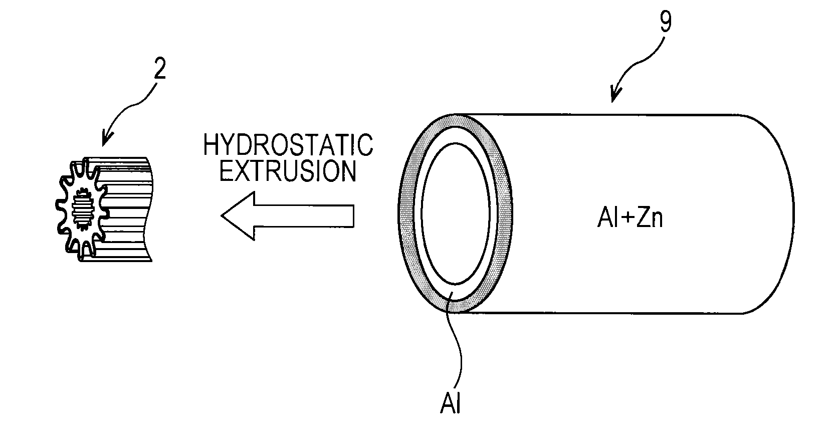
[0042]In this embodiment, a method for manufacturing the multi-layered fin tube 2 described in the first embodiment, and a forming device used in the manufacturing thereof will be described. FIG. 3 is a schematic view showing a method for manufacturing a multi-layered fin tube 2 according to the second embodiment. FIG. 4 (a) to FIG. 4 (c) are diagrams schematically showing a forming device used in the manufacturing of a multi-layered fin tube 2.
[0043]The outline of a manufacturing method of a multi-layered fin tube 2 will be described with reference to FIG. 3.
[0044]First, a cylindrical aluminum material is prepared as an inner tube material as a metal original material for forming the inner tube 4 of a multi-layered fin tube 2. A cylindrical aluminum alloy material that contains several percent (for example, 1 to 5%) zinc is prepared as an outer tube material as a metal original ...
third embodiment
[0058]A modification of the above-described multi-layered fin tube (multi-layered heat transfer tube) 2 according to the first embodiment will be described in detail with reference to FIG. 5 (a) and FIG. 5 (b). FIG. 5 (a) is a sectional view of a multi-layered fin tube 16 according to this modification taken along a plane perpendicular to the axis. FIG. 5 (b) is a perspective view showing the whole multi-layered fin tube 16.
[0059]As with the multi-layered fin tube 2 in the first embodiment, the multi-layered fin tube 16 is a substantially cylindrical hollow tube having a length, for example, of 4 to 6 m, and has a substantially cylindrical inner tube 17 as a base material that forms the main body of the multi-layered fin tube 16, and an outer tube 18 as a coating material that coats the entire outer peripheral surface of the inner tube 17. The inner tube 17 is formed, for example, of metallic aluminum, and the outer tube 18 is formed of aluminum alloy that contains several percent (...
PUM
| Property | Measurement | Unit |
|---|---|---|
| Thickness | aaaaa | aaaaa |
| Hydrostatic pressure | aaaaa | aaaaa |
Abstract
Description
Claims
Application Information
 - R&D
- Intellectual Property
- Life Sciences
- Materials
- Tech Scout
- Unparalleled Data Quality
- Higher Quality Content
- 60% Fewer Hallucinations
Browse by: Latest US Patents, China's latest patents, Technical Efficacy Thesaurus, Application Domain, Technology Topic, Popular Technical Reports.
© 2025 PatSnap. All rights reserved.Legal|Privacy policy|Modern Slavery Act Transparency Statement|Sitemap|About US| Contact US: help@patsnap.com


