Light emitting diode type illuminating module

a technology of light-emitting diodes and illuminating modules, which is applied in the direction of lighting and heating apparatus, lighting support devices, light source combinations, etc., can solve the problems of large amount of heat generated, rapid reduction of light intensity, environmental pollution, etc., and achieve high light efficiency and high power

Inactive Publication Date: 2013-03-14
AHN IN KYU +1
View PDF16 Cites 22 Cited by
  • Summary
  • Abstract
  • Description
  • Claims
  • Application Information

AI Technical Summary

Benefits of technology

[0025]Accordingly, the present invention has been devised to solve the above-mentioned problems, and an object of the present invention is to provide an LED-type illuminating module, wherein high-power light emitting diodes (LEDs) having high light efficiency, a small LED disposition area and a high power per LED are used as a light source, a radiating structure for radiating the heat generated from the high power LEDs is composed of a radiating body and a plurality of radiating fins, and the radiating structure, including the radiating body and the radiating fins provided in steps around the radiating body, is made of a magnesium alloy that is a light metal alloy having a thermal diffusivity that is 1.7 times higher than that of aluminum, thereby providing a small high-power LED-type illuminating module, so that users can easily fabricate middle- or high-power illuminating apparatuses having a power of several tens of watts to several hundreds of watts and can use these illumination devices, and the radiation can be carried out in steps by the radiating body and the plurality of radiating fins, with the result that the radiation performance of the high-power LED-type illuminating module can be greatly improved, and the volume of the high-power LED-type illuminating module can be greatly reduced, thereby decreasing the size and weight thereof and greatly decreasing the production cost thereof, and, particularly, when a relatively high-power illuminating apparatus such as a floodlight, security light or the like is fabricated using such LED-type high-power illuminating modules, only a necessary number of the LED-type high-power illuminating modules are directly installed in a support, a reflector, a case or the like to obtain a desired illumination output, thus greatly reducing the production cost thereof and preventing the waste of resources.

Problems solved by technology

Therefore, they are problematic in that energy consumption is high for lightness, and in that the lifecycle is short, so the light intensity rapidly decreases, thereby requiring periodic control.
Particularly, since the above-mentioned lights use mercury gas, there is a problem in that they cause environmental pollution when they are discarded.
However, since conventional illuminating apparatuses using light emitting diodes (LEDs) are difficult to solve the problems of heat radiation, low-capacity light emitting diodes (LEDs) having a power consumption of 1 watt or less have generally been used.
In other words, when high-capacity light emitting diodes (called power LEDs) having a power consumption of 1 watt or more, particularly, 2˜10 watts are used, a large amount of heat is generated.
In this case, when the heat radiation performance thereof is low, peripheral devices are damaged by heat and the lifecycle thereof is rapidly shortened, so that these conventional illuminating devices cannot practically serve as illuminators.
However, such illuminating devices as traffic lights, security lights, street lights, floodlights, lights for houses or cattle pens, lights for sign boards, downlights, etc. are disadvantageous in that their properties are deteriorated by thermal stress and they easily break down.
That is, when the amount of electric current flowing to a plurality of light emitting diodes (LEDs) increases so that they can be operated, the amount of heat generated therefrom increases, thus causing the properties of the illuminating apparatuses to deteriorate and causing the illuminating apparatuses to break down.
The printed circuit board (PCB) malfunctions and breaks down by the thermal stress generated from the LEDs.
However, in this case, there is a problem in that, due to the metal material constituting the radiating plate, the thickness and volume of the radiating plate increase in order to meet required heat radiating efficiency, which increases the size and weight of each of the illuminating apparatuses.
Moreover, in the case of conventional light emitting diode type illuminating modules or street lights, since it is possible to prevent the entry of moisture only when they are tightly closed, it is difficult to install a cooler for efficient heat radiation.
Nevertheless, installing a cooler causes the problem of all kinds of foreign materials including water or moisture being introduced from the exterior into such illuminating apparatuses as traffic lights, security lights, street lights, floodlights, lights for houses or cattle pens, etc.
Meanwhile, when a radiator used in a light emitting diode type illuminating module is formed by die-casting aluminum, there are problems in that the thickness and volume thereof are increased, so that the production cost thereof is increased and the weight thereof cannot be decreased, thus causing the production cost of a lamp stay or a lamp support heavier than a conventional discharge lamp to increase, and in that a previously-installed lamp stay or lamp support must be replaced by another.
Moreover, when a conventional discharge-type security light, floodlight or the like is replaced by a light emitting diode type security, floodlight or the like, the original light does not have a sufficient space in which to install a radiator required by the light emitting diode type security light, floodlight or the like, so that it cannot be directly used and is discarded, thereby causing the problem of a waste of resources.
However, they are problematic in that the volume and weight thereof are increased.
Further, conventional radiators using a principle of a heat spreader (called a self-powered heat pump) have lately been applied to high-price products such as notebooks and the like and LED illuminating apparatuses even though they have high performance but a short lifecycle, are expensive and have a large volume.
However, they are problematic in that the prices of illuminating apparatuses become excessively expensive when they are used in the illuminating apparatuses.
However, they are problematic in that thermal diffusion is restricted in tightly-enclosed spaces, and in that the air layer located at the narrow space between the thin films has a thermal insulating effect.
However, among the above two cases, in the case where a power supply converter is independently and directly provided in the LED-type illuminating module, there is a problem in that the heat generated from the power supply converter provided in the LED-type illuminating module cannot be easily radiated because the power supply converter is installed in a housing formed of general synthetic resin having very low thermal diffusivity and thermal conductivity, and the heat generated from light emitting diodes (LEDs) can also be radiated only by a radiator, thus shortening the lifecycle of the LED-type illuminating module including the power supply converter and the light emitting diodes (LEDs).
However, conventionally, similarly to a low-power illuminating module having a power of 8 W or less, heat radiation is carried out only by one radiator integrated with several radiating fins, so that the size of the radiator becomes large or the heat radiation efficiency thereof becomes low at the same size, thereby shortening the lifecycle of the illuminating module itself including light emitting diodes (LEDs).

Method used


Image

  • Light emitting diode type illuminating module
  • Light emitting diode type illuminating module
  • Light emitting diode type illuminating module

Examples


Embodiment Construction

[0065]Hereinafter, preferred embodiments of the present invention will be described in detail with reference to the attached drawings.

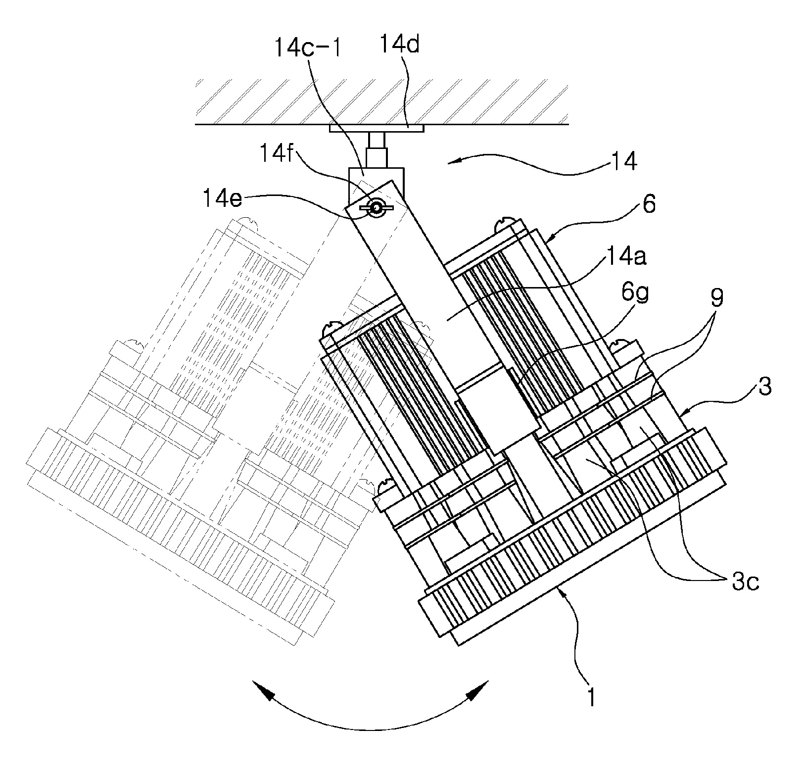
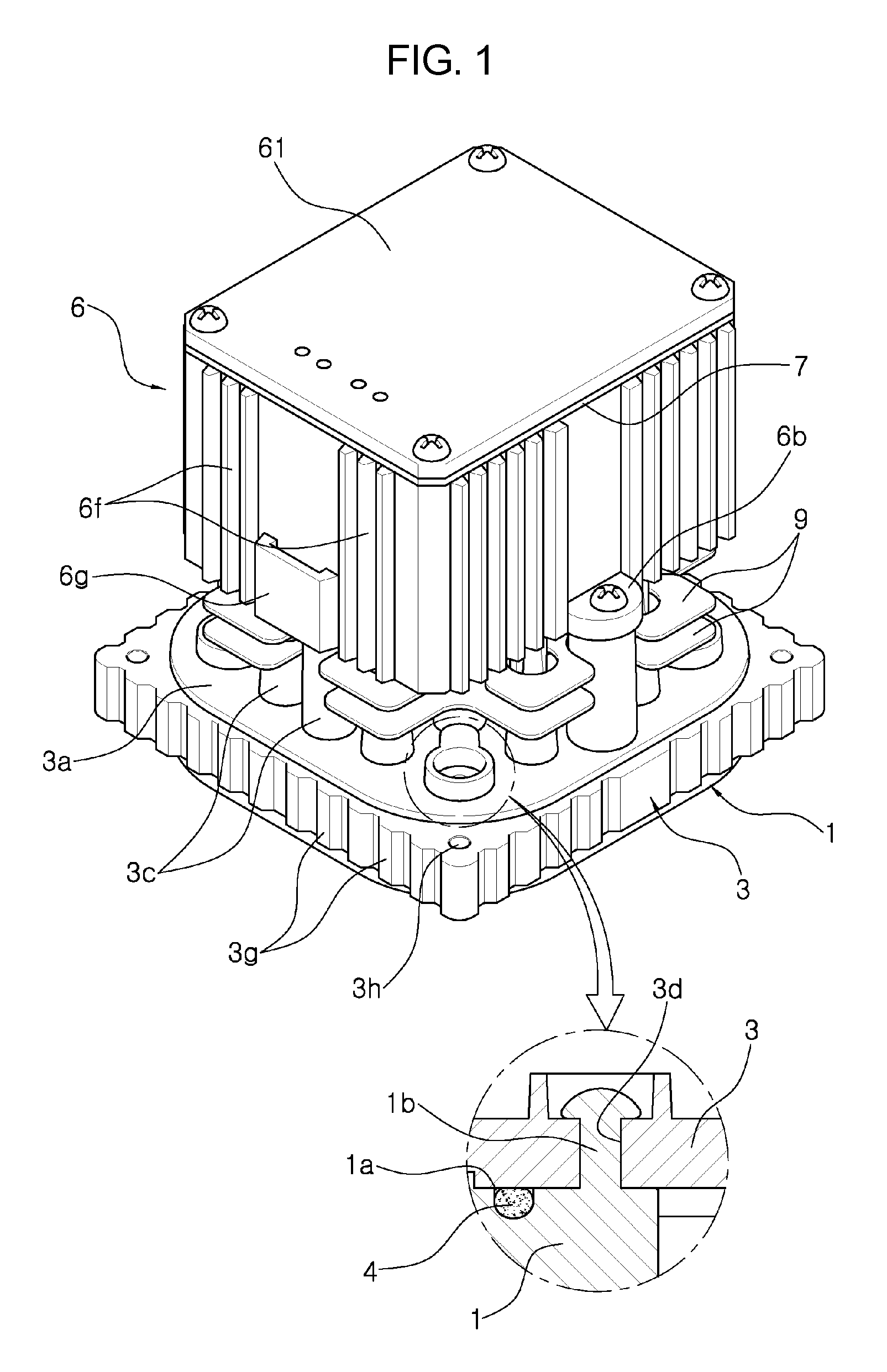
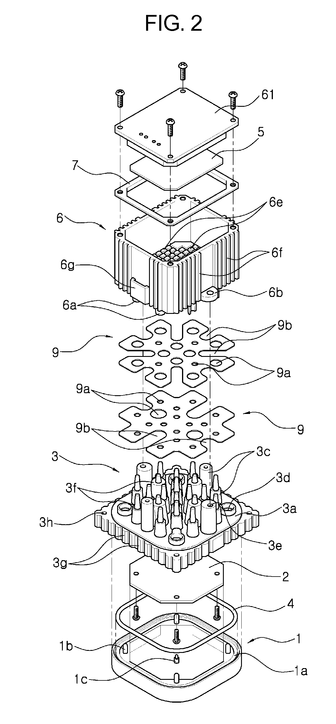
[0066]First, as shown in FIGS. 1 and 2, the present invention provides an LED-type illuminating module, which independently functions as an illuminating apparatus and which is used to constitute various kinds of illuminating apparatuses having desired outputs by providing the plurality of LED-type illuminating modules on a module fixing plate 8 having a predetermined area, including: a light transmission or diffusion plate 1; an LED substrate 2 on which LEDs 2a are fixed at regular intervals by soldering; a radiator 3 formed by die-casting a light metal alloy; a waterproof ring 4; a plurality of radiating plates 9 made of a light metal alloy; a housing 6 formed by injection-molding a conductive polymer resin material; a waterproof packing 7; and a power supply converter 5.

[0067]In this case, the light transmission or diffusion plate 1 is formed by inj...


PUM

PropertyMeasurementUnit
melting pointaaaaaaaaaa
poweraaaaaaaaaa

Abstract

Disclosed herein is an LED-type illuminating module, which independently functions as an illuminating apparatus and which is used to constitute various kinds of illuminating apparatuses having desired outputs by providing a plurality of the LED-type illuminating modules on a module fixing plate 8 of a predetermined area, including: a light transmission or diffusion plate; an LED substrate on which LEDs are fixed at regular intervals by soldering; a radiator formed by die-casting a light metal alloy; a waterproof ring; a plurality of radiating plates made of a light metal alloy; a housing formed by injection-molding a conductive polymer resin material; a waterproof packing; and a power supply converter.

Description

BACKGROUND OF THE INVENTION[0001]1. Technical Field[0002]The present invention relates to a light emitting diode type illuminating module having a capacity of from several watts to several tens of watts, and, more particularly, to a multipurpose light emitting diode type illuminating module which can greatly improve the heat radiation performance of an illuminating apparatus and can reduce the weight and size thereof because light emitting diodes (LEDs) generating a small amount of heat and having low power consumption as a light source are used.[0003]2. Description of the Related Art[0004]Generally, conventional security lights and street lights use a mercury or sodium lamp as their light source. Therefore, they are problematic in that energy consumption is high for lightness, and in that the lifecycle is short, so the light intensity rapidly decreases, thereby requiring periodic control.[0005]Particularly, since the above-mentioned lights use mercury gas, there is a problem in tha...

Claims


Application Information

Patent Timeline
Patent Type & Authority Applications(United States)
IPC IPC(8): F21V29/00F21V11/00
CPCF21V29/2293F21V29/89F21V21/088F21V3/0436F21V17/101F21V19/004F21V19/0055F21V23/006F21V23/008F21V23/023F21Y2105/001F21V21/30F21Y2101/02F21W2131/103F21K9/13F21S2/00F21V21/045F21S8/03F21V29/507F21V29/713F21V29/81F21V29/83F21V31/005F21Y2113/00F21K9/23F21K9/238F21Y2105/10F21Y2115/10F21V3/062F21V19/001F21V19/0075F21V31/00F21V29/15
Inventor AHN, IN-KYULEE, SEUL-KI
Owner AHN IN KYU
Why Eureka
Try Eureka