Image processing device, image processing method, and imaging device
a technology of image processing and image quality, applied in the field of image processing techniques, can solve the problems of loss of resolution, image quality impairment, and drop in s/n ratio of captured images, and achieve the effects of reducing resolution loss, high sensitivity, and high s/n ratio
- Summary
- Abstract
- Description
- Claims
- Application Information
AI Technical Summary
Benefits of technology
Problems solved by technology
Method used
Image
Examples
first embodiment
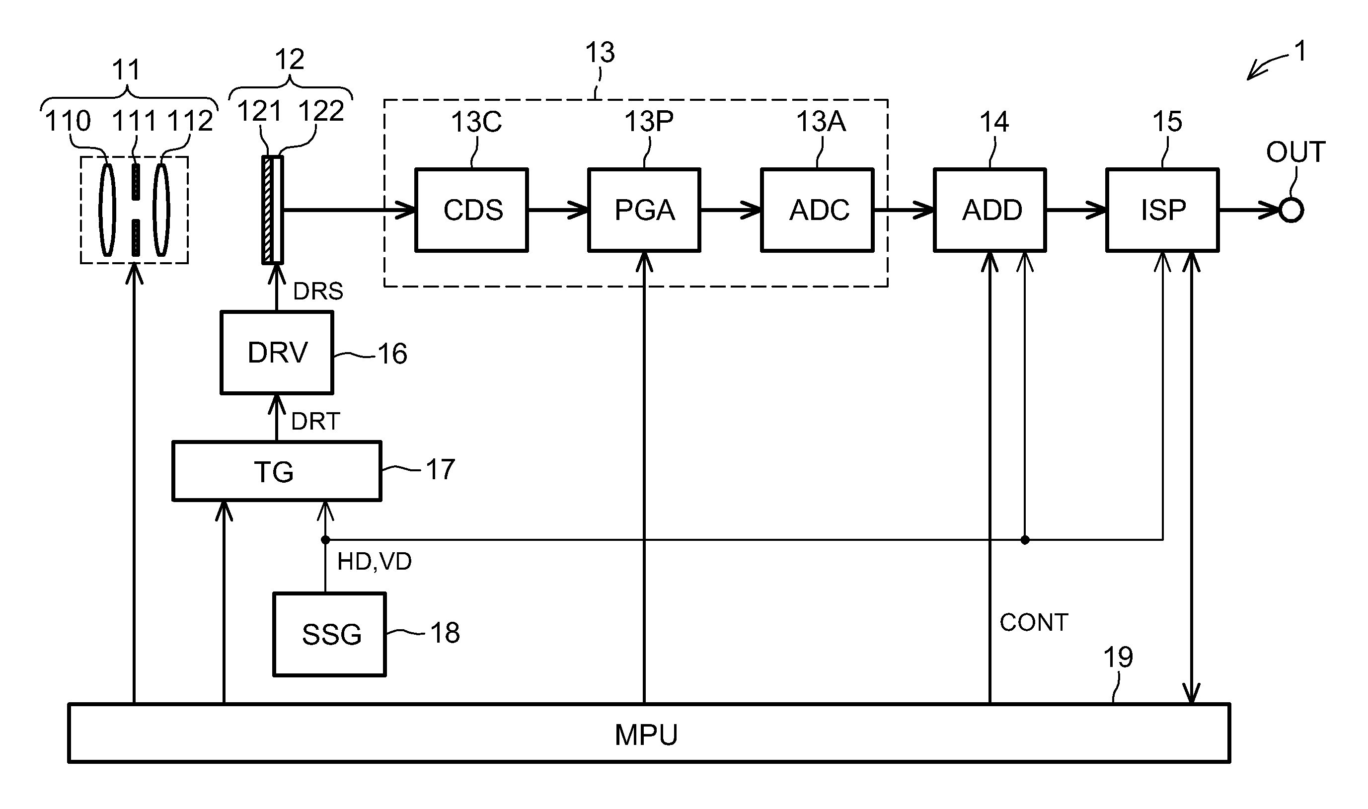
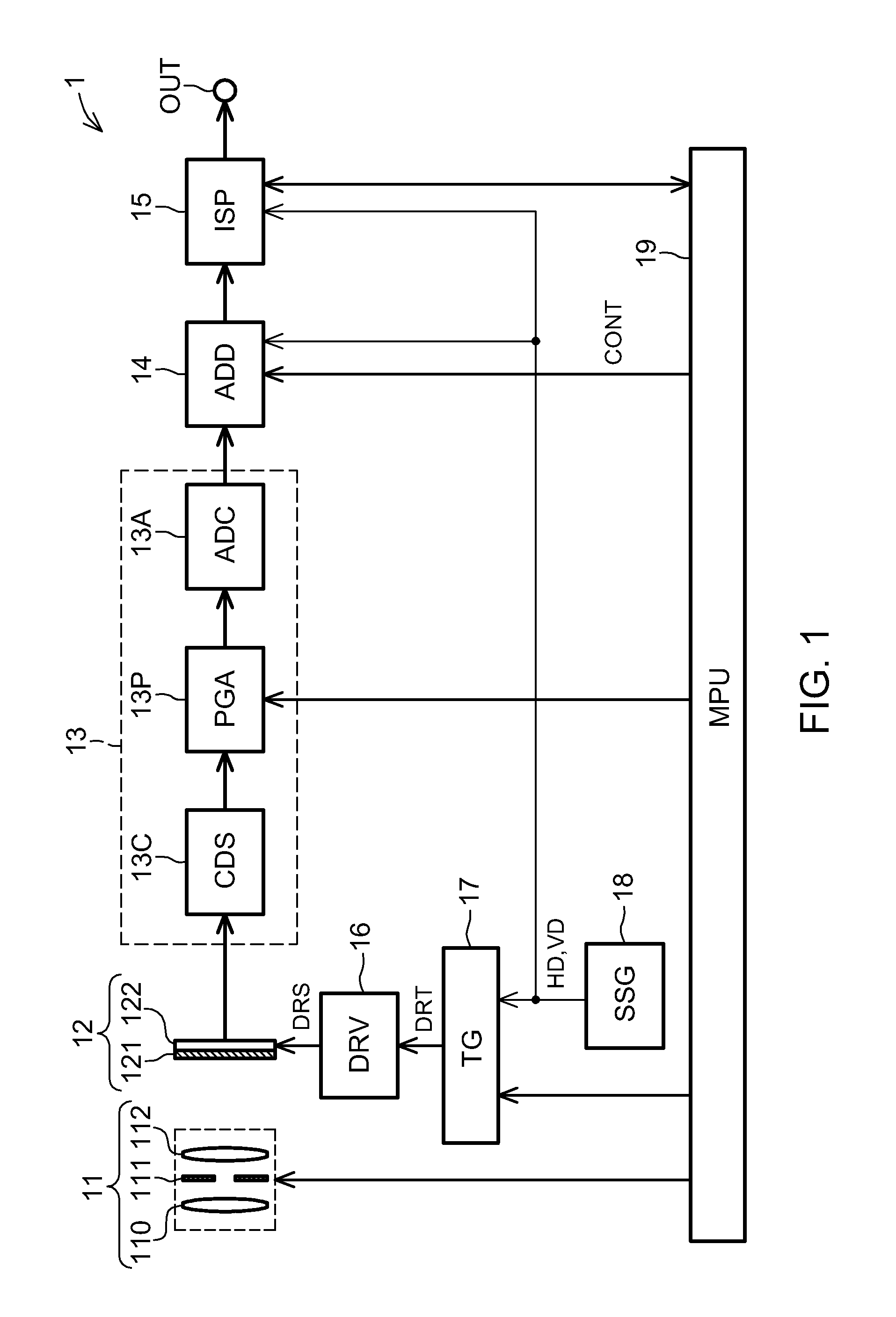
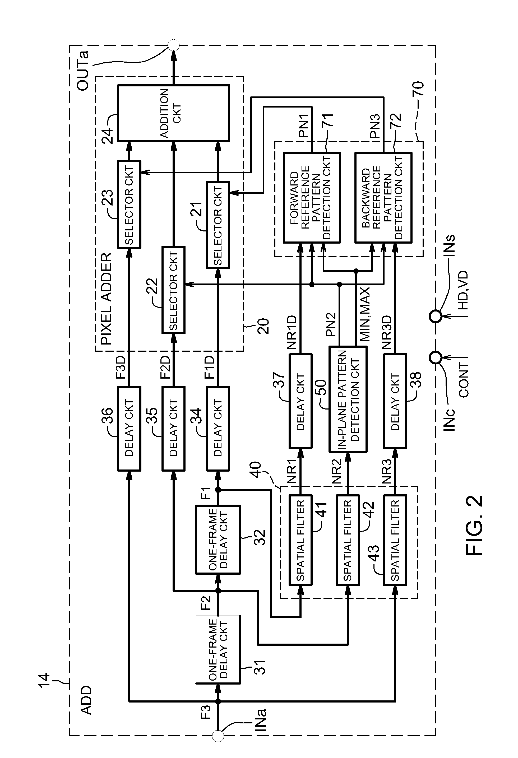
[0130]FIG. 1 is a block diagram showing the general structure of an imaging device 1 according to a first embodiment of the invention. The imaging device 1 shown in FIG. 1 has imaging optics (a lens unit) 11, a CCD image sensor 12, a front end section 13, a pixel adding circuit (image processing device) 14, an image signal processor (ISP) 15, a drive circuit (DRV) 16, a timing generator (TG) 17, a synchronization signal generator (SSG) 18, and a microprocessing unit (MPU) 19 that functions as a control unit. The imaging optics 11 include a front lens 110, a diaphragm 111, and a rear lens 112.
[0131]The CCD image sensor 12 is a single plane solid-state imager having a single color filter array 121 and a single CCD device 122. The color filter array 121 has N types of color filters (where N is an integer equal to or greater than two) arrayed in a periodic manner in a plane. These filters transmit light of colors in N mutually differing wavelength regions. The color filter array 121 use...
second embodiment
[0334]FIG. 97 is a block diagram showing the general structure of the imaging device 2 in a second embodiment of the present invention. This imaging device 2 differs from the imaging device 1 in the first embodiment in having a different MPU 19B and an additional image detection circuit 81. The second embodiment has the same effects as the first embodiment.
[0335]The image detection circuit 81 operates in synchronization with the horizontal synchronization signal HD and vertical synchronization signal VD supplied from the synchronization signal generator 18 and detects the luminance level or ‘speed’ of the corrected image signal output by the pixel adding circuit 14. The image detection circuit 81 has, for example, an integration function and an average level detection function. The integration function calculates an integrated value Ep by adding up the corrected pixel values in an effective pixel region included in the output signal of the pixel adding circuit 14 over a given number...
third embodiment
[0368]FIG. 99 is a block diagram showing the general structure of the imaging device 3 in a third embodiment of the present invention. This imaging device 3 differs from the imaging device 1 in the first embodiment in having a different MPU 19C and an additional light meter 82. The third embodiment has the same effects as the first embodiment.
[0369]The light meter 82 is operative to detect the subject illumination by measuring light striking the imaging surface of the CCD image sensor 12 or the imaging optics 11. The light meter 82 has an illumination sensor (not shown) that is mounted in a position determined with reference to the optical axis of the imaging optics 11.
[0370]In addition to the functions of the MPU 19 in the first embodiment, the MPU 19C has the function of controlling the exposure control parameters in accordance with the detected subject illumination value supplied from the light meter 82. More specifically, the MPU 19C can control the f-stop value of the diaphragm...
PUM
 Abstract
Description
Claims
Application Information
 - R&D
- Intellectual Property
- Life Sciences
- Materials
- Tech Scout
- Unparalleled Data Quality
- Higher Quality Content
- 60% Fewer Hallucinations
Browse by: Latest US Patents, China's latest patents, Technical Efficacy Thesaurus, Application Domain, Technology Topic, Popular Technical Reports.
© 2025 PatSnap. All rights reserved.Legal|Privacy policy|Modern Slavery Act Transparency Statement|Sitemap|About US| Contact US: help@patsnap.com


