
High speed laser crystallization of particles of photovoltaic solar cells

a technology of photovoltaic solar cells and laser crystallization, which is applied in the direction of manufacturing tools, sustainable manufacturing/processing, and final product manufacturing, etc., can solve the problems of non-selective heating, degrade the conversion efficiency of photons and electrons, and traditional crystallization techniques used in the photovoltaic (pv) industry, etc., to achieve rapid processing, enhance the conversion efficiency of thin film photovoltaics, and reduce the cost

Inactive Publication Date: 2013-04-18
PURDUE RES FOUND INC
View PDF5 Cites 2 Cited by
  • Summary
  • Abstract
  • Description
  • Claims
  • Application Information

AI Technical Summary

Benefits of technology

The patent describes a new and improved method for making thin film solar cells using a process called high speed laser crystallization (HSLC). This method allows for larger crystals to be formed, resulting in faster and more efficient solar cells. It also promotes the growth of dense crystals and reduces damage to the part being processed. Compared to conventional techniques, HSLC offers faster production rates, selective processing, energy savings, and the ability to densify packed crystals without complicated temperature control systems. Overall, the HSLC method provides a low-cost and rapid way to make thin film solar cells with better conversion efficiency.

Problems solved by technology

Defects such as grain boundary and point defects in current thin film photovoltaics (PVs) degrade the photon-electron conversion efficiency and transportation of electrons.
Traditional crystallization techniques used in the photovoltaic (PV) industry, such as Rapid Thermal Annealing (RTA) techniques, have several limitations.
These limitations can include issues regarding non-selective heating, slow crystal growth, temperature control for large crystal growth, and the need to use costly vacuum / inert gas environments.

Method used


Image

  • High speed laser crystallization of particles of photovoltaic solar cells
  • High speed laser crystallization of particles of photovoltaic solar cells
  • High speed laser crystallization of particles of photovoltaic solar cells

Examples


Embodiment Construction

[0020]For the purposes of promoting an understanding of the principles of the novel technology, reference will now be made to the exemplary embodiments described herein and illustrated in the drawings and specific language will be used to describe the same. It will nevertheless be understood that no limitation of the scope of the novel technology is thereby intended, such alterations and further modifications in the illustrated devices and methods, and such further applications of the principles of the novel technology as illustrated therein being contemplated as would normally occur to one skilled in the art to which the novel technology relates.

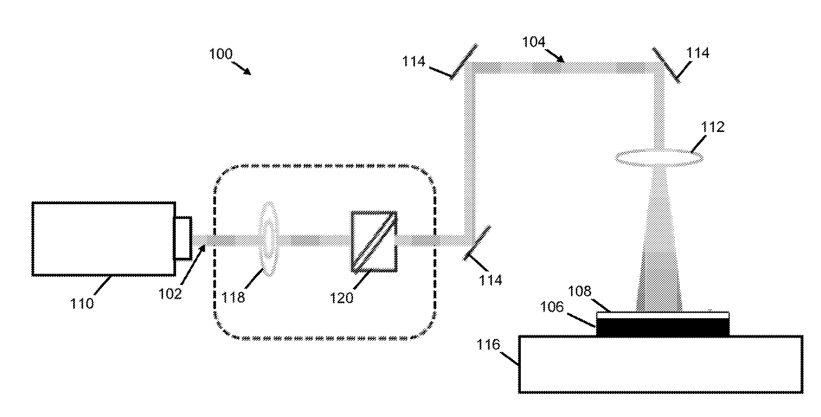
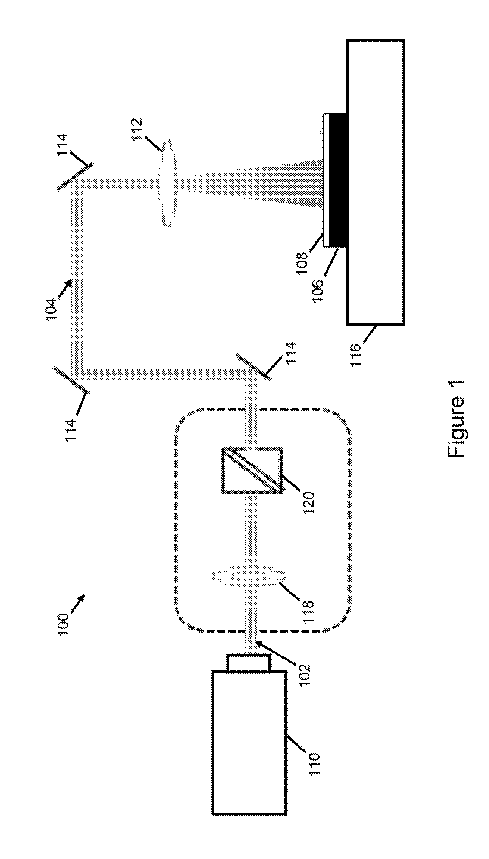
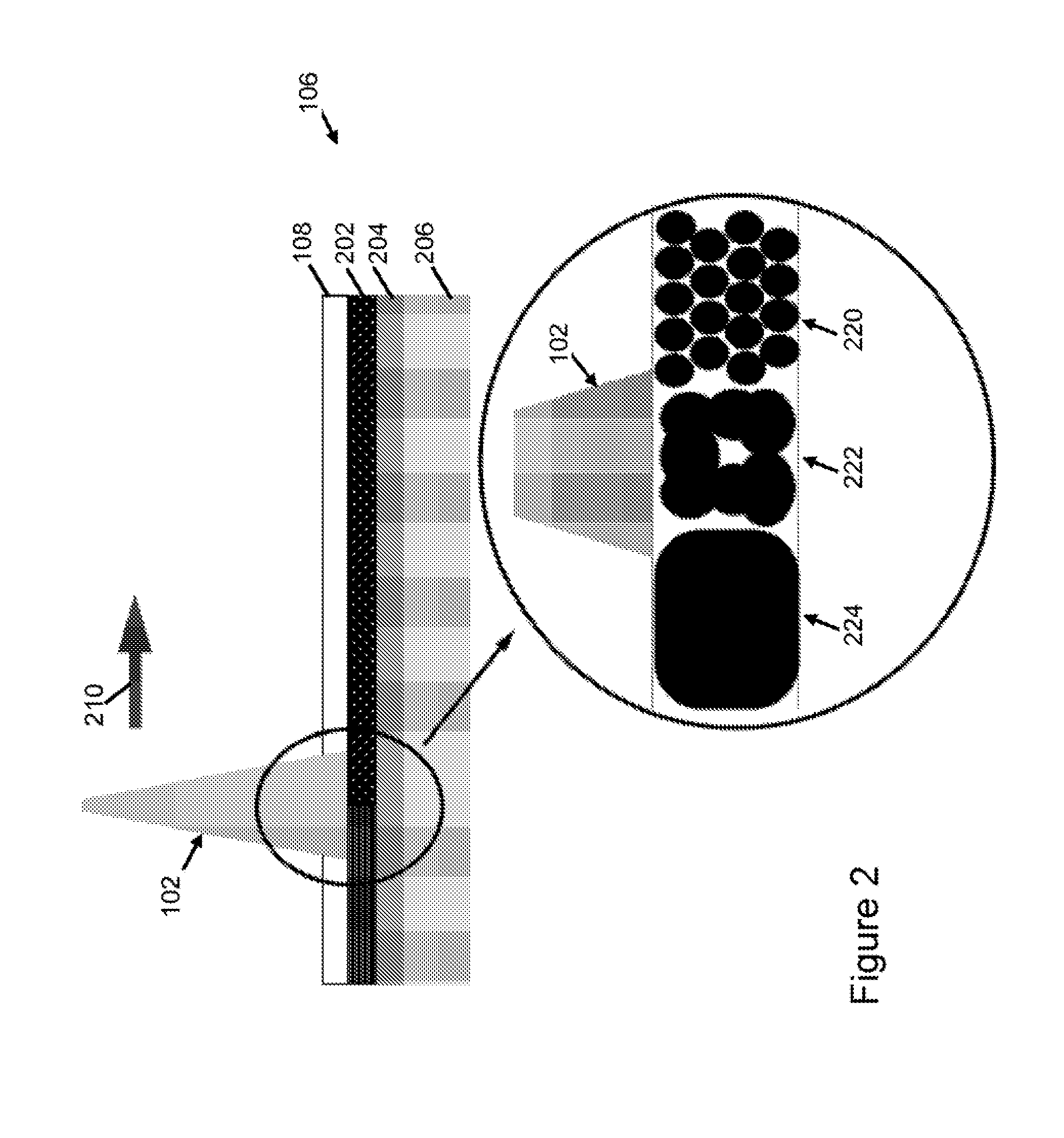
[0021]The high speed laser crystallization (HSLC) method uses a pulsed laser to crystallize thin films under a transparent confinement layer. This can provide several benefits over traditional methods, some of these benefits can include: 1) selectivity: the wavelength of the laser can be tuned to just heat the desired materials and not affe...


PUM

PropertyMeasurementUnit
Pressureaaaaaaaaaa

Abstract

A system and method for enhancing the conversion efficiency of thin film photovoltaics. The thin film structure includes a photovoltaic absorbent layer covered by a confinement layer. A laser beam passes through the confinement layer and hits the photovoltaic absorbent layer. The laser can be pulsed to create localized rapid heating and cooling of the photovoltaic absorbent layer. The confinement layer confines the laser induced plasma plume creating a localized high-pressure condition for the photovoltaic absorbent layer. The laser beam can be scanned across specific regions of the thin film structure. The laser beam can be pulsed as a series of short pulses. The photovoltaic absorbent layer can be made of various materials including copper indium diselenide, gallium arsenide, and cadmium telluride. The photovoltaic absorbent layer can be sandwiched between a substrate and the confinement layer, and a molybdenum layer can be between the substrate and the photovoltaic absorbent layer.

Description

CROSS REFERENCE TO RELATED APPLICATIONS[0001]This is a division patent application of co-pending U.S. patent application Ser. No. 13 / 113,386, filed May 23, 2011.BACKGROUND OF THE INVENTION[0002]The present invention generally relates to material processing methods via high speed laser crystallization, and more particularly to methods for enhancing the conversion efficiency of thin film photovoltaics by increasing crystal size and decreasing the defects of the light absorbent layer.[0003]The conversion efficiency of thin film solar cells depends on the crystallinity of the light absorbent layer (e.g., cadmium telluride (CdTE), copper indium selenide (CIS) and copper indium gallium selenide (CIGS)). Defects such as grain boundary and point defects in current thin film photovoltaics (PVs) degrade the photon-electron conversion efficiency and transportation of electrons. Traditional crystallization techniques used in the photovoltaic (PV) industry, such as Rapid Thermal Annealing (RTA) ...

Claims


Application Information

Patent Timeline
IPC IPC(8): B23K26/00
CPCH01L31/0322H01L31/1872B23K26/0066H01L31/03923Y02E10/544H01L31/1836H01L31/1852Y02E10/541H01L31/03925Y02P70/50B23K26/352
Inventor CHENG, GARY J.ZHANG, MARTIN YIYANG, YINGLING
Owner PURDUE RES FOUND INC
Learn More