Method and apparatus for using pressure cycling and cold liquid co2 for releasing natural gas from coal and shale formations

Inactive Publication Date: 2013-05-02
ENIS BEN M +1
View PDF5 Cites 27 Cited by
  • Summary
  • Abstract
  • Description
  • Claims
  • Application Information

AI Technical Summary

Benefits of technology

[0046]The present invention relates to a method and apparatus for capturing the flue gas of a coal fired power plant, incinerator or chemical processing plant, and separating the CO2 gas therefrom, and converting the CO2 gas captured from the power plant into a cold pressurized liquid CO2, and injecting it under pressure into an underground stratum or layer of coal and/or gas shale, and in particular, releasing the pressurized liquid CO2 through perforat

Problems solved by technology

This pressure causes the rock formation to crack, allowing the fracturing fluid to enter and extend through the formations.
Because drilling a borehole typically involves using a rotating drill bit, chips and particles of rock are often produced that can adversely affect the passage of fluid through the wellbore, resulting in reduced permeability and flow of fluid into the borehole.
Thus, considerable environmental concerns have arisen, including the possibility that chemicals and other waste fluids might bleed into water aquifers, as well as the possible erosion and deformation that can result once fractures have been created and resources have been removed.
Environmental and health concerns associated with hydraulic fracturing include contamination of ground water, risks to air quality, the migration of gases and chemicals to the surface, the creation of seismic events, and the potential mishandling of waste.
Surface Mining: During surface mining, methane is typically released into the atmosphere as the overlying rock strata are removed, although for this type of release, no emissions mitigation options are currently being used.
However, the low gas content of most surface mines relative to that of underground mines makes it unlikely that significant r

Method used


Image

  • Method and apparatus for using pressure cycling and cold liquid co2 for releasing natural gas from coal and shale formations
  • Method and apparatus for using pressure cycling and cold liquid co2 for releasing natural gas from coal and shale formations
  • Method and apparatus for using pressure cycling and cold liquid co2 for releasing natural gas from coal and shale formations

Examples


Embodiment Construction

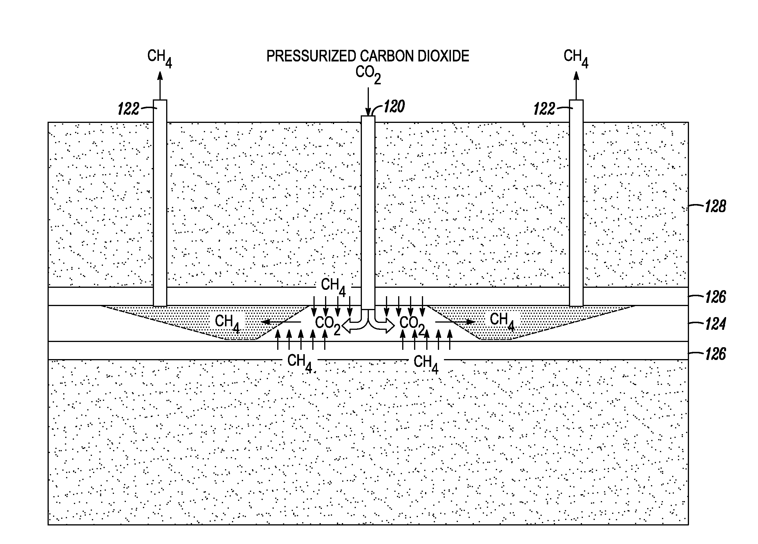
[0131]The proposed approach preferably comprises capturing, pressurizing, chilling and liquefying the CO2 effluent from a coal fired power plant, incinerator or chemical processing plant and then introducing the pressurized CO2 in liquid form (LCO2) into a coal stratum or a gas shale stratum that will sequester the LCO2. There will also be natural gas recovered from the site including after the CO2 has been adsorbed into the coal or shale and natural gas has been released therefrom, which can be sold to offset the cost of sequestering the CO2. If these strata are located adjacent to the power plant, the LCO2 is preferably directly inserted into the strata. If these strata are located a distance from the power plant, the captured CO2 is preferably collected onto a truck trailer or into a pipeline, etc., for transport to the strata site. In either case, natural gas can be recovered for sale.

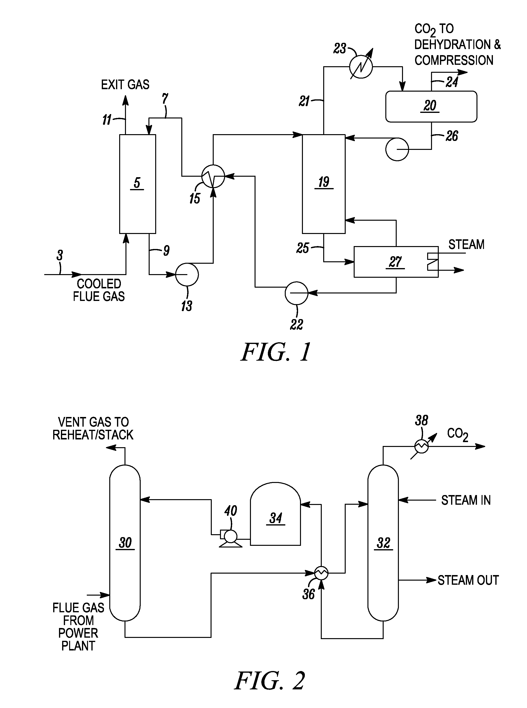
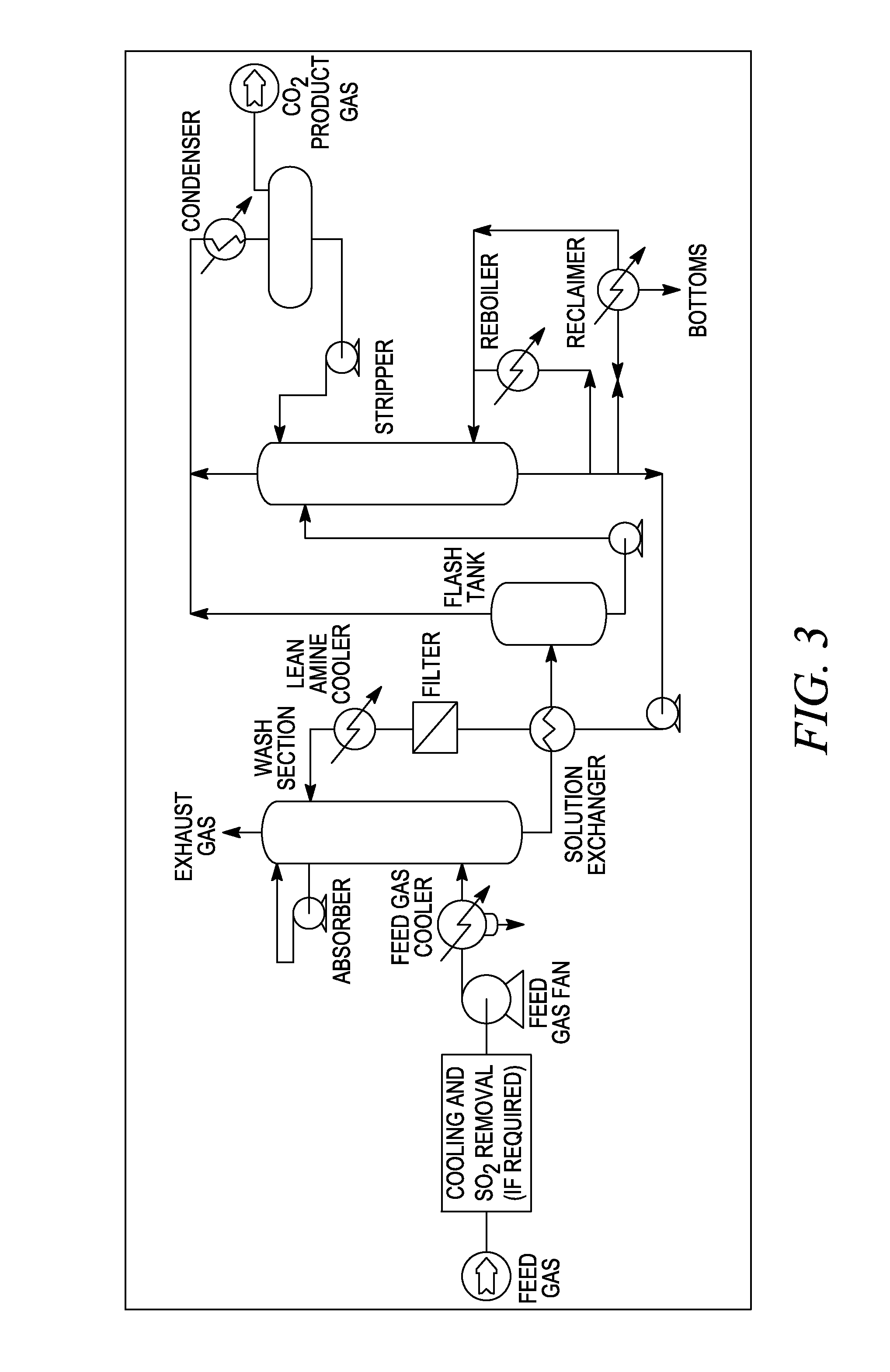
[0132]Separation of carbon dioxide gas (CO2) from the flue gases of a power plant, incinerator ...


PUM


Abstract

The invention relates to a method and apparatus for sequestering CO2 gas and releasing natural gas from underground coal and/or gas shale formations using CO2 gas captured from the flue gas of a coal burning power plant, and processing it to produce cold liquid pressurized CO2, and injecting the cold liquid CO2 under pressure to create fractures within the formation and causing the CO2 to be adsorbed into the coal or gas shale and CH4 to be desorbed, released and recovered. A special pressure cycling process is used to enable the pressure within the formation to be increased and decreased, including allowing the LCO2 to change phase to a GLO2, and injecting LCO2 under pressure repeatedly, which causes greater expansion of the proliferation zone within the formation, and more efficiently releases CH4.

Description

RELATED APPLICATIONS[0001]This application incorporates by reference U.S. Provisional Application Ser. No. 61 / 284,960, filed on Dec. 28, 2009, and U.S. application Ser. No. 12 / 930,117, filed Dec. 28, 2010, and U.S. Provisional Application Ser. No. 61 / 553,166, filed Oct. 29, 2011.FIELD OF THE INVENTION[0002]The invention relates to a method and apparatus for using pressure cycling and liquid CO2 to release methane from coal and shale formations, and in particular, to using cold liquid CO2 and injecting it under pressure above the fracture gradient to create fractures within the formation and then to reduce the pressure to allow cleats to form within the formation and then to repeat the cycle using cold liquid CO2 again, to cause CO2 to be adsorbed and CH4 to be desorbed, wherein methane can be released and recovered from the formation.BACKGROUND OF THE INVENTION[0003]Hydraulic fracturing is a process that creates fractures in rock formations (or reservoirs), which has the effect of i...

Claims


Application Information

Patent Timeline
IPC IPC(8): E21B43/16
CPCE21B41/0064E21B43/006Y02P90/70E21B43/26Y02C20/40E21B43/2605E21B43/164
Inventor LIEBERMAN, PAUL
Owner ENIS BEN M
Why Eureka
Try Eureka