Vehicle Battery Pack Thermal Barrier

Active Publication Date: 2013-06-20
TESLA INC
View PDF37 Cites 70 Cited by
  • Summary
  • Abstract
  • Description
  • Claims
  • Application Information

AI Technical Summary

Benefits of technology

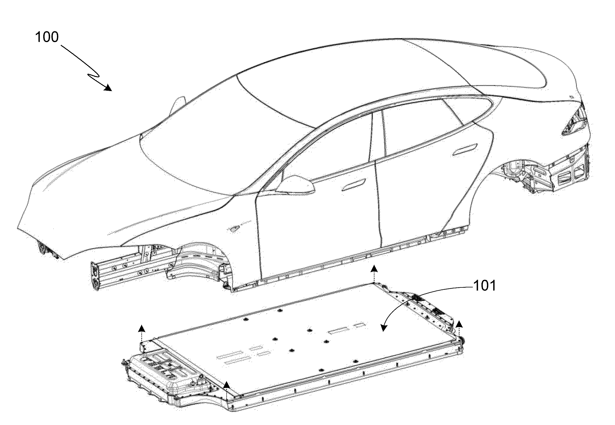
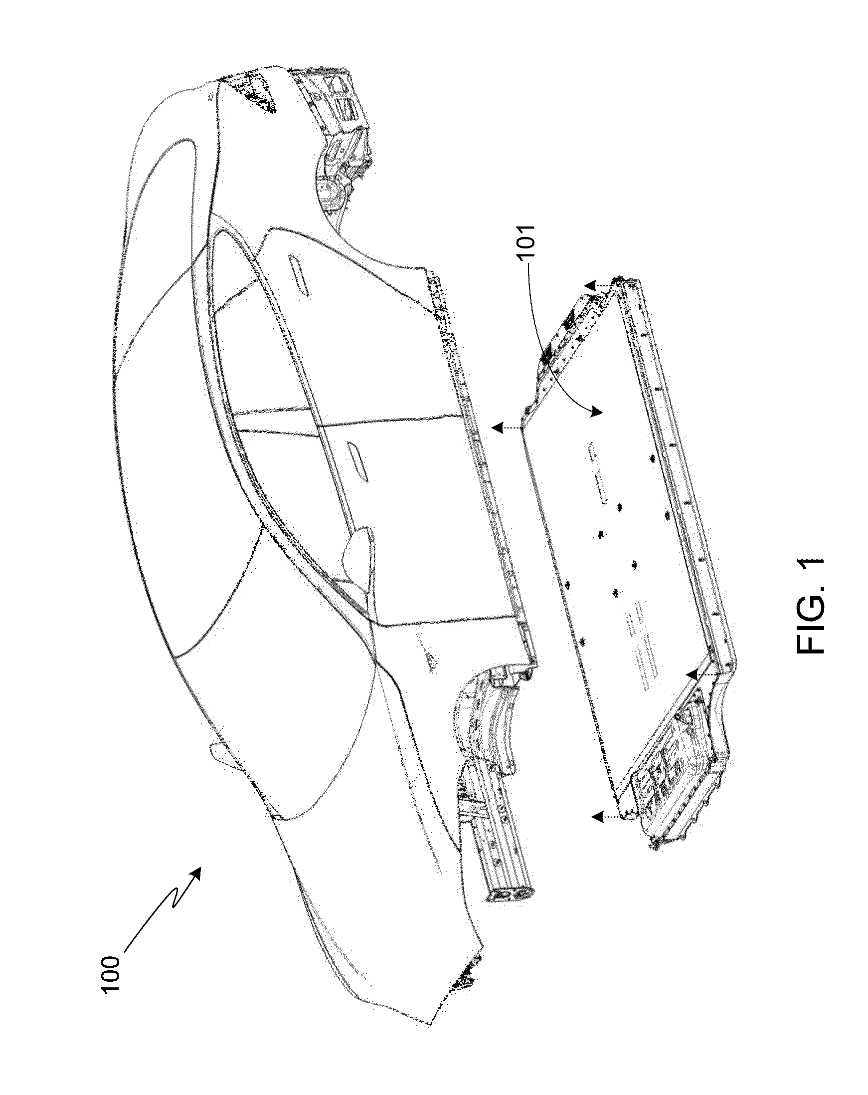
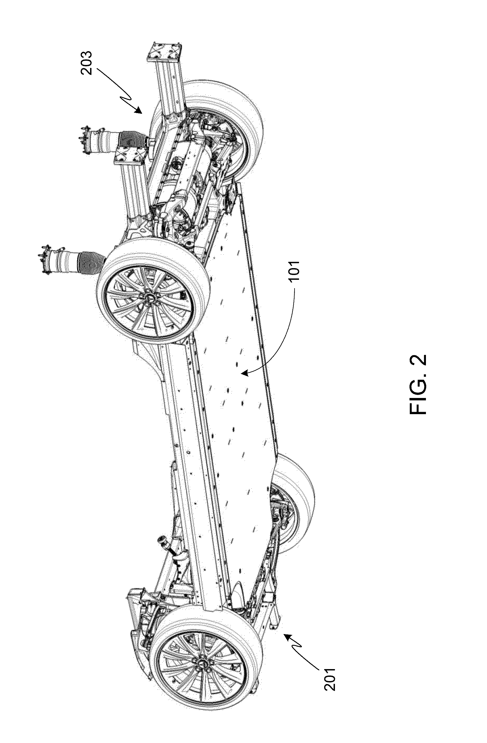
[0009]The present invention provides a vehicle battery pack integrated assembly, the assembly utilizing a battery pack enclosure that includes an enclosure top panel, an enclosure bottom panel, and a plurality of enclosure side members, where the battery pack enclosure is configured to hold a plurality of batteries, and where the battery pack is mounted between the passenger cabin floor panel and the driving surface. The system assembly includes a multi-layer thermal barrier interposed between the battery pack enclosure and the passenger cabin floor panel, where the multi-layer thermal barrier provides noise isolation, thermal isolation and vibration damping, where the multi-layer thermal barrier is compressed when the battery pack enclosure is moun

Problems solved by technology

The use of such vehicles, more specifically the use of vehicles which rely on fossil fuels, e.g., gasoline, creates two problems.
First, due to the finite size and limited regional avai

Method used


Image

  • Vehicle Battery Pack Thermal Barrier
  • Vehicle Battery Pack Thermal Barrier
  • Vehicle Battery Pack Thermal Barrier

Examples


Embodiment Construction

[0033]In the following text, the terms “battery”, “cell”, and “battery cell” may be used interchangeably and may refer to any of a variety of different battery types, chemistries and configurations including, but not limited to, lithium ion (e.g., lithium iron phosphate, lithium cobalt oxide, other lithium metal oxides, etc.), lithium ion polymer, nickel metal hydride, nickel cadmium, nickel hydrogen, nickel zinc, silver zinc, or other battery type / configuration. The term “battery pack” as used herein refers to multiple individual batteries contained within an enclosure, the individual batteries electrically interconnected to achieve the desired voltage and capacity for a particular application. As such, the terms “battery pack” and “battery pack enclosure” may be used interchangeably herein. The term “electric vehicle” as used herein may refer to an all-electric vehicle, also referred to as an EV, a plug-in hybrid vehicle, also referred to as a PHEV, or a hybrid vehicle, also refer...


PUM


Abstract

An integration assembly for a battery pack mounted between the passenger cabin floor panel of an electric vehicle and the driving surface is provided, the assembly utilizing a multi-layer thermal barrier interposed between the battery pack enclosure and the passenger cabin floor panel, where the multi-layer thermal barrier provides noise isolation, thermal isolation and vibration damping, and where the multi-layer thermal barrier is compressed when the battery pack enclosure is mounted to the vehicle. The multi-layer thermal barrier is comprised of a first layer formed from a compressible and conformable elastic material and a second layer formed from a conformable thermally insulating material. The multi-layer thermal barrier may also include a moisture barrier layer that encases the first and second layers, for example a moisture barrier layer fabricated from a plastic. A sealant may be used to seal and bond the moisture barrier layer to the battery pack enclosure.

Description

CROSS-REFERENCE TO RELATED APPLICATION[0001]The present application is a continuation-in-part of U.S. patent application Ser. No. 13 / 311,343, filed 5 Dec. 2011, and claims benefit of the filing date of U.S. Provisional Patent Application Ser. No. 61 / 426,254, filed 22 Dec. 2010, the disclosures of which are incorporated herein by reference for any and all purposes.FIELD OF THE INVENTION[0002]The present invention relates generally to vehicle structures and, more particularly, to means for isolating the battery pack of an electric vehicle from the passenger compartment.BACKGROUND OF THE INVENTION[0003]A large percentage of the world's vehicles run on gasoline using an internal combustion engine. The use of such vehicles, more specifically the use of vehicles which rely on fossil fuels, e.g., gasoline, creates two problems. First, due to the finite size and limited regional availability of such fuels, major price fluctuations and a generally upward pricing trend in the cost of gasoline...

Claims


Application Information

Patent Timeline
IPC IPC(8): B60K1/04
CPCB60K1/04B62D25/025F41H7/042B62D29/008B62D25/2036B60K2001/0438B60Y2306/11B60Y2410/114
Inventor RAWLINSON, PETER DOREHERRON, NICHOLAS HAYDENEDWARDS, BRUCE PHILLIPGOETCHIUS, GREGORY MICHAEL
Owner TESLA INC
Why Eureka
Try Eureka